 English
 Vietnamese
 Italian
 Spanish
 Thai
Thai Japanese
 Portuguese
 Korean
 Russian
 French
 German
 Polish
 Indonesian
Why Compatible Inductors Always Matter for EMI Filtering
Compatible inductors play a crucial role in emi filtering by shaping circuit behavior and supporting regulatory compliance. Recent studies show that inductor core materials and design choices directly influence power efficiency and signal integrity in modern circuits.
· Ferrite and iron powder cores help maintain efficiency and reduce losses.
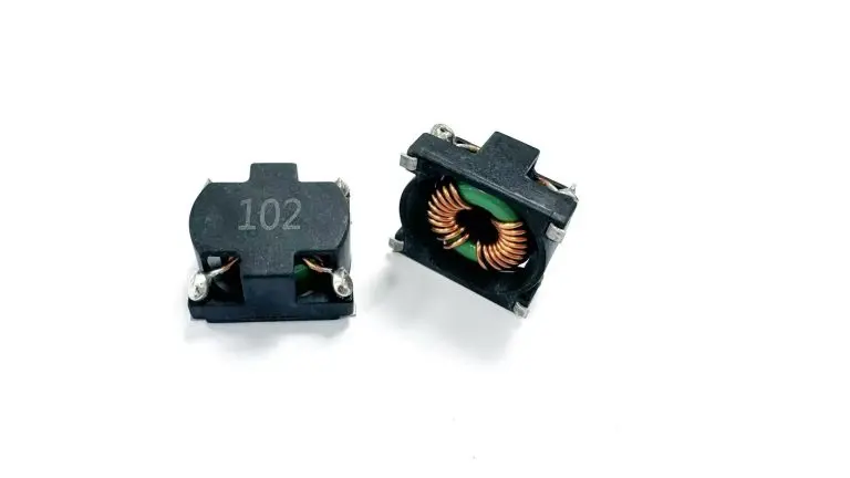
· Toroidal and bobbin-based designs boost performance in high-frequency environments, which strengthens emi suppression.
· Selecting the right inductors ensures that circuits operate reliably and meet strict standards.
What Are Compatible Inductors in EMI Filtering

Defining Compatibility for EMI Filters
Compatible inductors form the backbone of effective emi filters. These components must match the electrical and mechanical requirements of the circuit to ensure reliable suppression of interference. Compatibility means more than just fitting into a circuit board. It involves aligning the inductor’s characteristics with the specific needs of emi filtering, such as the target frequency range, current handling, and integration with other filter components.
Manufacturers specify compatibility for inductors used in emi filters by considering several important factors:
· Inductance value must align with the target noise frequency band to ensure effective impedance.
· Current ratings, including both saturation and RMS, are crucial to prevent core saturation and manage thermal rise.
· DC resistance impacts efficiency and heat generation in the filter stage.
· Self-resonant frequency should exceed the highest noise frequency to maintain inductive behavior.
· Package size, mounting style, and shielding effectiveness affect both electrical performance and mechanical integration.
Note: Engineers must always verify that the inductor’s self-resonant frequency sits above the highest frequency of concern. This ensures the filter continues to block interference rather than allowing it to pass.
Compatible inductors also need to work seamlessly with filter capacitors. This partnership helps create a low-pass or common-mode filter that blocks unwanted interference while allowing desired signals to pass. In power supply applications, the right inductor prevents radiated emi and supports compliance with regulatory standards.
Key Parameters for EMI Suppression
The performance of emi filters depends on several key electrical parameters. Each parameter influences how well the filter blocks interference and maintains signal integrity.
· Inductance affects the inductor's energy storage capability and determines the filter’s ability to suppress noise.
· Quality Factor (Q) indicates efficiency. A higher Q means lower losses and better performance in emi filters.
· Rated Current determines the maximum current the inductor can handle without overheating or saturating the core.
· Distributed Capacitance impacts stability. Lower capacitance leads to better performance in high-frequency applications.
The table below summarizes how these parameters impact emi filter performance:
Parameter | Impact on EMI Filters |
Inductance | Sets impedance; blocks interference at target frequencies |
Quality Factor (Q) | Higher Q reduces losses; improves filter efficiency |
Rated Current | Prevents overheating and core saturation |
Distributed Capacitance | Lower values improve high-frequency filtering |
In real-world applications, engineers select compatible inductors that meet all these requirements. They consider the type of interference, such as conducted or radiated emi, and choose filters that address the specific challenges of their designs. When filters use the right inductors, they achieve reliable suppression of interference and maintain compliance with industry standards.
Critical Factors When Choosing the Right EMI Filter Inductor
Inductance Value and Tolerance
Inductance value stands as a primary factor in EMI filters. It determines the impedance at different frequencies, which directly affects the filter's ability to reduce unwanted noise. Higher inductance values enhance suppression at elevated frequencies. Lower values may require additional capacitance to achieve the desired level of filtering. Engineers must select inductors with precise inductance values to match the requirements of their circuits.
Tolerance variation also plays a significant role in EMI filter performance. Small mismatches can increase insertion loss and cause ripple in the passband. In higher-order filters, tight tolerances are necessary to maintain performance. Impedance mismatches may create reflections that degrade signal quality. Precise tuning becomes critical to avoid ripple and ensure reliable suppression of interference.
Current Rating and Saturation
Current rating defines the maximum current an inductor can handle without overheating or saturating. EMI filters must use inductors with ratings that match or exceed the maximum input current. This prevents failure due to overcurrent conditions. The table below shows how current rating impacts filter selection in different applications:
Current Rating Range | Implication for EMI Filters |
Less than 1 amp | Suitable for low-power applications |
Over 1000 amps | Required for high-power applications |
Must match or exceed maximum input current | Prevents failure due to overcurrent conditions |
Core saturation presents several risks in EMI filters. When saturation occurs, inductance collapses, leading to increased current ripple and filter failure. Thermal runaway risks arise as losses increase, causing higher temperatures and earlier saturation. Distorted output waveforms affect the stability of current shapes. Non-linear magnetic behavior increases interference, complicating compliance with strict limits.
Consequence | Description |
Thermal Runaway Risks | Increased losses lead to higher temperatures, causing earlier saturation and potential failure. |
Distorted Output Waveforms | Saturation causes visible distortion in waveforms, affecting the stability of current shapes. |
Reduced Inductance | As saturation occurs, inductance collapses, leading to increased current ripple and filter failure. |
EMI Challenges | Non-linear behavior of the magnetic field increases noise, complicating compliance with strict limits. |
Core Material and Losses
Core material selection influences losses and EMI suppression. Ferrite cores offer cost-effective solutions for frequencies from 150 kHz to 30 MHz. Nanocrystalline cores provide higher saturation flux density and better high-frequency performance. Amorphous metal cores deliver excellent properties for specialized applications. Engineers must choose core materials that minimize losses and meet the requirements of their EMI filters.
Core Material | Properties |
Ferrite | Cost-effective, suitable for 150 kHz–30 MHz |
Nanocrystalline | Higher saturation flux density, better high-frequency performance |
Amorphous metal | Excellent high-frequency properties for specialized applications |
Core losses impact EMI suppression and circuit efficiency. Molded inductors contain magnetic flux, minimizing leakage and preventing interference with sensitive circuits. Low DC resistance results in less power wasted as heat, enhancing overall efficiency. Superior magnetic shielding reduces EMI in densely packed PCBs.
Advantage | Description |
Effective EMI Reduction | Molded inductors contain magnetic flux, minimizing leakage and preventing interference with sensitive circuits. |
Low DC Resistance (DCR) | Lower DCR results in less power wasted as heat, enhancing overall circuit efficiency. |
Superior Magnetic Shielding | The design effectively shields against external magnetic fields, reducing EMI in densely packed PCBs. |
Frequency Response and Impedance
Frequency response characteristics are essential for EMI filters in RF and power applications. Engineers must consider inductance value, Q factor, self-resonant frequency, DC resistance, current rating, tolerance, parasitic capacitance, and package size. These specifications determine how well the filter suppresses interference and maintains signal integrity.
Specification | What It Means | Why It Matters in RF Circuits |
Inductance Value | The rated inductance of the component, usually in nH or µH | Sets the basic reactance and circuit response |
Q Factor | Shows how low-loss the inductor is at a certain frequency | Higher Q normally reduces RF loss and improves tuning efficiency |
Self-Resonant Frequency | The frequency where the inductor resonates with its internal parasitic capacitance | Determines the upper useful frequency range of the component |
DC Resistance | The internal resistance of the conductive path | Higher DCR causes voltage drop, power loss, and heating |
Current Rating | The maximum current the inductor can safely handle | Prevents excessive temperature rise, value change, or reliability problems |
Tolerance | How close the actual inductance is to the rated value | Affects matching accuracy, filter response, and resonant frequency |
Parasitic Capacitance | Unwanted capacitance inside the component and around its mounting pads | Affects SRF, impedance, and high-frequency behavior |
Package Size | The physical size and mounting style | Affects Q, SRF, DCR, current rating, and PCB parasitics |
Impedance matching between inductors and capacitors is crucial for filter performance. Mismatched impedances can significantly reduce filter effectiveness. Engineers must ensure proper impedance matching during the design and installation of EMI filters. This practice helps block interference and maintain signal quality.
· Impedance matching is crucial for filter performance.
· Mismatched impedances can lead to a significant reduction in filter effectiveness.
· Proper impedance matching should be ensured during the design and installation of impedance filters.
Size, Mounting, and Efficiency
Size and mounting constraints affect the selection of compatible inductors in compact designs. Engineers must choose mounting methods that fit the requirements of their EMI filters and applications. The table below outlines common mounting methods and their uses:
Mounting Method | Description | Applications |
Horizontal Mounting | Places inductors on their sides, suitable for larger toroids. | UPS, line reactors, industrial power modules. |
Vertical Mounting | Saves space on PCBs, cost-efficient, uses plastic supports. | Power modules in computers, telecom, lighting. |
Through Hole Mounting | Enhances stability and current capacity, supports both orientations. | Heavy-duty industrial electronics, automotive. |
Surface Mounting (SMD) | Minimizes assembly time, maximizes placement density, supports miniaturization. | Personal electronics, aerospace computing. |
High-quality, efficient inductors support modern compact designs and power efficiency. Power inductors are essential for efficient energy transmission, minimizing energy loss during the transfer of electrical energy. Selecting high-quality power inductors can lead to significant reductions in operating costs for businesses. Efficient inductors minimize energy loss during operation, which is essential for maintaining efficiency in various applications. In electric vehicles, efficient power inductors can significantly reduce energy loss, thereby extending the driving range. In smartphones, they contribute to longer battery life and reduced heat generation. Ferrite core inductors manage electrical energy by efficiently storing and releasing it, which minimizes losses. The high magnetic permeability of ferrite cores is crucial for ensuring smooth operation in high-frequency applications.
Engineers must select compatible inductors that meet the requirements of EMI filters, support impedance matching, and fit the size and mounting constraints of their designs. These choices ensure reliable suppression of interference, compliance with standards, and efficient operation in modern devices.
Step-by-Step Guide to Choosing the Right EMI Filter
Identify EMI and Compliance Requirements
Engineers and hobbyists must start by understanding the filtering requirements for their designs. Regulatory standards set the baseline for acceptable interference levels. The process for identifying these requirements involves several steps:
1. Conduct pre-compliance testing to spot potential EMI issues early.
2. Develop a test plan that outlines standards, equipment, and acceptance criteria.
3. Prepare the product in its intended operating mode.
4. Set up test equipment and the product according to the plan.
5. Execute tests, monitor results, and record any anomalies.
6. Analyze test data to confirm compliance.
7. Generate a report detailing procedures and results.
8. Implement corrective actions if failures occur.
9. Re-test after making corrections.
Evidence Description | Impact on EMI Filter Inductor Selection |
Regulatory standards dictate performance requirements for conducted emissions. | They determine necessary insertion loss and component ratings, influencing inductor choice in EMI filters. |
Focus on the 150 kHz–30 MHz band for conducted emissions. | This band is critical for compliance, affecting filter performance and inductor selection. |
Safety approvals and creepage/clearance distances are essential for reliability. | These factors ensure electrical safety and compliance, impacting the design and selection of inductors in EMI filters. |
Analyze Circuit and System Needs
Before choosing the right emi filter, engineers must analyze the circuit and system characteristics. Key factors include:
· Types of noise, such as common-mode and differential-mode interference.
· Frequency ranges of operation.
· Current ratings for the application.
· Thermal performance under load.
· Application-specific requirements, including safety standards and leakage current limits.
Selecting the correct core material also matters. Ferrite suits most 150 kHz–30 MHz applications. Nanocrystalline cores offer higher saturation flux density and better high-frequency performance. Amorphous metal cores provide excellent properties for specialized filtering requirements.
Match Inductor Specs to Application
Matching inductor specifications to the application ensures effective suppression of interference. The table below highlights how different specs impact emi filtering:
Specification | Impact on EMI Filtering |
Inductance Value | Must be sized correctly to limit Pass-Band Impedance. |
Current Ratings | Must meet application-specific current requirements. |
Compliance Standards | Ensures effective suppression of electromagnetic interference. |
Choosing the right emi filter early in the design cycle prevents costly revisions. Engineers must consider operating frequency, current levels, and the configuration of passive emi filters. Failing to align specs with application needs can result in inadequate noise suppression and increased voltage drop.
Evaluate Manufacturer Data and Quality
Reviewing manufacturer data helps confirm that inductors meet filtering requirements. Important criteria include:
Criteria | Description |
Electrical ratings | Confirm line voltage, current rating with derating, mains frequency, and operating temperature range. |
EMC performance | Review insertion loss curves for common-mode and differential-mode attenuation across specified frequencies. |
Safety and leakage | Check for required certifications and standards, including limits for earth and patient leakage. |
Mechanical fit | Consider the mounting type and its implications on space, airflow, and wiring convenience. |
High-quality inductors improve the reliability of emi filters in demanding applications.
Test and Validate Inductor Selection
Testing and validation confirm that the chosen emi filters meet all requirements. Best practices include:
1. Identify noise sources and their frequency ranges.
2. Select high-quality components with suitable specifications.
3. Place filters close to noise sources to minimize radiated emi.
4. Minimize parasitic effects by using short, direct PCB traces.
5. Use shielding to further reduce interference.
6. Test filter performance with spectrum analyzers and network analyzers.
7. Adjust the configuration as needed for optimal filtering.
Tip: Always match inductors with capacitors to create effective passive emi filters. This combination blocks unwanted interference and ensures compliance with standards.
Checklist for Choosing the Right EMI Filter:
· Define filtering requirements and compliance standards.
· Analyze circuit noise and system needs.
· Match inductor specs to the application and configuration.
· Review manufacturer data for quality and fit.
· Test and validate filter performance in real-world conditions.
Common Pitfalls in EMI Filter Inductor Selection
Overlooking Frequency and Impedance
Many engineers make the mistake of not considering the full frequency range when designing emi filters. Filters that do not target the right frequencies allow interference to pass through, reducing the effectiveness of filtering. Impedance mismatches between filters and other components can also weaken suppression. When filters do not match the system’s impedance, interference can reflect back into the circuit, causing unexpected noise and performance issues. Engineers should always verify that filters block interference across the required frequency spectrum.
Ignoring Core Saturation and Losses
Core saturation and losses often go unnoticed during emi filter selection. When the core material saturates, the filter loses its ability to block interference. This leads to increased current ripple and possible filter failure. High core losses generate heat, which can damage filters and nearby components. Engineers must select filters with core materials that handle the expected current without saturating. They should also consider losses to maintain reliable filtering in all applications.
Mismatched Inductance or Current Rating
Selecting filters with the wrong inductance or current rating can cause serious problems. Mismatched inductance may result in voltage overshoots that exceed the breakdown voltage of sensitive components. Parasitic inductance can create ringing, which generates additional interference and disrupts nearby systems. Filters with insufficient current ratings may overheat or fail during operation. Increased switching losses can occur, leading to prolonged periods of high voltage and current. Engineers must match the inductance and current rating of filters to the needs of their applications to ensure effective filtering and circuit reliability.
Neglecting Size or Mounting Constraints
Some engineers focus only on electrical properties and ignore physical constraints. Filters that do not fit the available space or mounting method may not perform as intended. Poor mounting can lead to mechanical stress, reduced heat dissipation, and even filter failure. Engineers should always consider the size and mounting requirements of filters, especially in compact or high-density applications.
Using Generic or Incompatible Inductors
Using generic or incompatible inductors in emi filters often leads to insufficient filtering and increased interference. Filters designed without considering the specific needs of the application may lack proper isolation between circuits. Neglecting inrush current effects, voltage surges, or the need for ESD protection can compromise the performance of filters. Engineers should avoid selecting filters based only on size or cost. Instead, they should choose filters tailored to the unique requirements of their applications to ensure reliable suppression of interference.
Tip: A careful review of common mistakes can help engineers avoid costly design errors and achieve robust emi suppression.
Most common mistakes in emi filter selection include:
1. Insufficient filtering
2. Lack of isolation between circuits
3. Neglecting inrush current effects
4. Ignoring voltage surges
5. Not using ESD protection diodes
6. Choosing wrong inductance for application
7. Ignoring current rating margins
8. Overlooking DCR
9. Selecting based only on size
Real-World Impact of Compatible vs. Incompatible Inductors
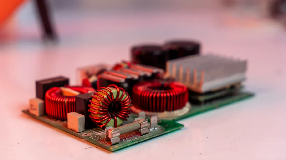
EMI Filter Success in Power Supplies
Case studies reveal how compatible inductors transform emi filters in power supply applications. Engineers often select inductors that match the electrical and mechanical requirements of their filters. This careful selection leads to reliable suppression of interference and improved compliance. The DOREXS Power Supply EMI Filter stands as a strong example. Engineers observed enhanced reliability and performance after integrating compatible inductors. These filters maintained stable operation and met regulatory standards. Real-world applications show that robust filter designs guide engineers toward effective solutions.
· Compatible inductors improve filter reliability.
· Filters achieve desired performance levels in power supply applications.
· Engineers develop compliant solutions by learning from successful case studies.
Filter Failure from Incompatible Inductors
Incompatible inductors often cause filter failures in emi filter applications. Engineers sometimes overlook key parameters, such as inductance value or current rating. Filters may allow interference to pass, leading to noise issues and regulatory non-compliance. One case involved a power supply filter that used a generic inductor. The filter failed to block interference, resulting in unstable operation and increased noise. Engineers replaced the inductor with a compatible model, which restored proper filtering and compliance.
Problem | Cause | Result |
Filter failure | Incompatible inductor | Increased interference |
Regulatory non-compliance | Incorrect inductance value | Noise issues |
Unstable operation | Insufficient current rating | Filter malfunction |
Lessons from Field Applications
Field applications teach engineers valuable lessons about emi filters. Engineers learn that compatible inductors play a critical role in blocking interference and maintaining signal integrity. Filters must match the needs of their applications to ensure reliable operation. Engineers who analyze real-world failures and successes develop better filter designs. They avoid common mistakes and select inductors that support robust filtering.
Tip: Engineers should always review case studies and field data before selecting inductors for emi filters. This practice helps prevent interference and ensures compliance in demanding applications.
Compatible inductors remain essential for effective EMI filtering and regulatory compliance. Engineers who follow a structured selection process achieve power efficiency, signal integrity, and reliable EMI suppression.
· Review circuit requirements
· Match inductor specifications
· Validate with manufacturer data
Applying these steps helps engineers build robust filters and avoid common mistakes. Reliable EMI suppression starts with careful component selection.
FAQ
What makes an inductor compatible for EMI filtering?
An inductor becomes compatible when its electrical and mechanical properties match the circuit’s needs. Engineers check inductance, current rating, core material, and frequency response to ensure reliable EMI suppression.
How does inductor type affect EMI filter performance?
Different inductor types, such as toroidal or multilayer chip, offer unique benefits. Toroidal inductors reduce leakage and support high-frequency filtering. Multilayer chip inductors fit compact designs and provide stable performance.
Why must engineers match inductors with capacitors in EMI filters?
Matching inductors with capacitors creates effective filters. This pairing blocks unwanted interference and allows desired signals to pass. Engineers achieve optimal suppression by selecting components that complement each other.
Can using a generic inductor cause EMI filter failure?
Yes. Generic inductors may lack proper ratings or suitable core materials. They often fail to block interference, leading to unstable operation and regulatory issues.
What is the role of core material in EMI suppression?
Core material determines loss and frequency response. Ferrite cores suit most EMI filters. Nanocrystalline and amorphous metals handle higher frequencies and reduce losses. Engineers select core materials based on application needs.