 English
 Vietnamese
 Italian
 Spanish
 Thai
Thai Japanese
 Portuguese
 Korean
 Russian
 French
 German
 Polish
 Indonesian
Rod inductor tips for easy troubleshooting at home
Many people feel unsure when they first encounter a rod inductor inside a device. They often believe that more voltage or a bigger antenna can solve every problem, but these ideas do not reflect proper circuit design. Some users think that if a device works in one place, it will work everywhere, which can lead to mistakes. Clear guidelines help anyone avoid these misconceptions and approach troubleshooting with safety and confidence. Simple steps and everyday tools allow most individuals to check the condition of a rod inductor at home.
· More voltage does not always increase performance.
· Bigger antennas are not always better.
· Devices may not work the same in every environment.
Identifying rod inductors
Visual signs of a rod inductor
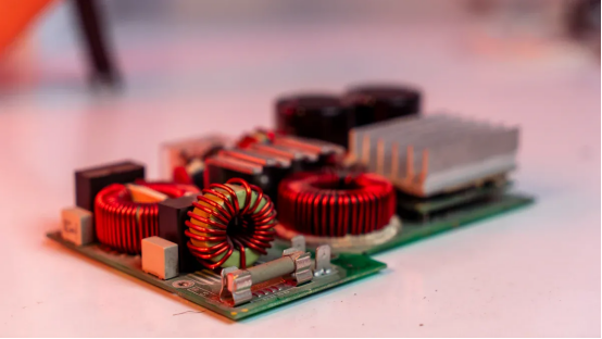
A rod inductor often appears as a small cylindrical component with wire wound around a central core. The coil usually has a dark or colored coating. Some devices use a plastic or ferrite rod as the core. These coils stand out because of their shape and the visible windings. The characteristics of a rod inductor include a compact design and a single-layer coil. Many people notice that the ends of the coil connect directly to the circuit board. The characteristics and functions of this component help filter signals and store energy in electronic circuits.
Where to find rod inductors in devices
Rod inductors appear in many home electronics. They often sit near power supply sections or radio frequency circuits. Devices such as radios, televisions, and chargers use these inductors to improve performance. The coil helps reduce noise and stabilize current. People can find these components close to other passive parts like resistors and capacitors. The functions of a rod inductor include blocking high-frequency signals and smoothing voltage. The inductor basics show that the coil works with other components to control the flow of electricity. The parameters of inductors, such as inductance and resistance, affect how well the device operates.
Checking size and value specs
The size and value of a rod inductor affect its characteristics and functions. People can check the markings on the body of the inductor to find important parameters. These markings show the inductance value, which tells how much energy the coil can store. The table below lists common inductor markings and their actual inductance values:
Inductor Marking | Actual Inductance Value |
4R7 | 4.7μH |
2R2 | 2.2μH |
100 | 10μH |
These parameters help users match the correct inductor to their device. The performance of the circuit depends on choosing the right inductance and coil size. The parameters of inductors, such as wire thickness and core material, also influence the overall performance. Understanding inductor basics and the main parameters allows anyone to identify and select the right component for repair or replacement.
Troubleshooting common issues
Physical damage and burns
Physical damage often affects the characteristics of an inductor. Users can spot problems by looking for discoloration, melted insulation, or burn marks on the coil. These signs usually indicate overheating or a short circuit. A damaged choke may show cracks or a broken core. People should check for a burnt smell near the rod inductor. This odor often points to a failed choke.
Tip: Always unplug the device before inspecting the inductor. Safety comes first.
A table helps summarize what to look for during a visual inspection:
Symptom | Possible Cause | Action Needed |
Burn marks | Overheating | Replace choke |
Melted insulation | Short circuit | Replace coil |
Cracked core | Mechanical stress | Replace choke |
Discoloration | Excessive current | Test inductance |
If the coil shows any of these symptoms, the inductor may not function as intended. Choke inductors with physical damage often lose their ability to filter signals. Inductance values may drop, which reduces performance.
Broken connections and loose windings
Loose windings or broken connections can cause a choke to fail. Users should gently move the coil with a non-metallic tool. If the coil shifts or feels loose, the windings may have separated from the core. A broken wire at the terminal also signals a problem.
· Check both ends of the coil for secure solder joints.
· Look for gaps between the wire and the core.
· Inspect the choke for missing or frayed wires.
Choke inductors rely on tight windings to maintain proper inductance. A loose coil changes the characteristics of the inductor. This change can lead to poor inductor performance. Devices may stop working or show reduced performance if the choke cannot maintain the correct inductance.
Note: Repairing a broken connection may restore the choke, but severe damage often requires replacement.
Device symptoms from inductor failure
Inductor failure can cause many device malfunctions. A faulty choke may lead to power loss, noise, or unstable operation. Radios may produce static, while chargers may stop working. The coil in a choke helps block unwanted signals. If the choke fails, the device may pick up interference or hum.
Common symptoms include:
· Sudden loss of power
· Increased noise or static
· Overheating of nearby components
· Flickering displays
Choke inductors with the wrong inductance value can disrupt the circuit. The device may not filter signals correctly. This problem affects the overall characteristics of the system. Users should compare the device's performance before and after replacing the choke. If the symptoms disappear, the inductor was likely the cause.
Alert: Always match the replacement choke to the original inductance value for best results.
Troubleshooting common issues with rod inductors helps users restore device performance. Careful inspection and testing of the coil, choke, and connections ensure reliable operation. Understanding how choke inductors work allows anyone to identify and fix basic problems at home.
Measurement of inductance
Using a multimeter for inductor testing
A multimeter provides a simple way to check the condition of an inductor at home. Many people use this tool to perform a basic measurement of inductance. The multimeter can measure resistance and continuity, which helps identify open or shorted coils. Some advanced models include a dedicated inductance measurement function.
To begin, set the multimeter to the correct mode. For basic testing, select the resistance setting. Place the probes on each end of the inductor. A healthy inductor will show a low resistance value. If the reading shows infinite resistance, the coil has an open circuit. A zero reading may indicate a shorted coil.
Tip: Always disconnect power before starting any measurement. This step prevents damage to the multimeter and protects the user.
Surface mount inductors require careful handling during testing. Their small size makes it easy to slip with the probes. Use tweezers to hold the component steady. For surface mount inductors, a magnifying glass helps ensure accurate probe placement.
Removing the rod inductor for accurate measurement
Removing the rod inductor from the circuit improves the accuracy of the measurement. Other components in the circuit can affect the reading. Capacitors and resistors connected in parallel or series may change the measured value. By isolating the inductor, the user can obtain a true measurement of inductance.
Follow these steps for best results:
1. Unplug the device and discharge any stored energy.
2. Use a soldering iron to carefully remove the rod inductor from the circuit board.
3. Allow the component to cool before handling.
4. Place the inductor on a non-conductive surface for measurement.
Surface mount inductors often require special tools for removal. Use a fine-tip soldering iron and tweezers to avoid damaging the pads. After removal, clean the leads to ensure a good connection during measurement.
Note: Removing the inductor prevents interference from other circuit elements. This practice leads to more reliable inductance measurement results.
Understanding test results
Interpreting the results of an inductance measurement helps determine the condition of the inductor. Compare the measured value to the original specifications. The characteristics of the inductor, such as inductance and resistance, should match the values marked on the component or listed in the device manual.
A table can help summarize what different readings mean:
Measurement Result | Possible Condition | Action Needed |
Matches spec | Inductor is healthy | Reinstall or reuse |
Much lower value | Shorted turns or damage | Replace inductor |
Much higher value | Broken wire or open coil | Replace inductor |
No reading | Open circuit | Replace inductor |
If the measurement of inductance falls outside the expected range, the inductor may have lost its performance. Surface mount inductors can show small changes in value due to their size, but large differences signal a problem.
Alert: Always use the correct replacement value to maintain circuit performance.
Inductance measurement provides valuable information about the health of the component. Accurate measurement ensures the device operates as designed. Testing and interpreting results allow users to restore proper function and avoid repeated failures. Understanding the characteristics of the inductor and the role of measurement in troubleshooting helps anyone maintain their electronics with confidence.
DIY inductor winding and repair
Adjusting turns and core material
Homemade inductor projects often begin with diy inductor winding. People can change the inductance by adjusting the number of turns on the coil. The following points show how this adjustment works:
· Increasing the number of turns in the coil raises the inductance.
· A coil with 150 turns can reach an inductance of 2.061 mH, or 2,061 uH.
· Fewer turns result in lower inductance.
Core material also plays a key role in inductor construction. Ferrite rods increase inductance more than air cores. Many adjustable inductors use ferrite or iron powder cores to fine-tune performance. Those who follow an inductor construction tutorial learn that both the number of turns and the core material affect the final value. Adjustable inductors allow users to match the coil to the needs of the circuit.
Simple repair tips for rod inductors
Repairing a rod inductor at home requires patience and basic tools. People often start by unwinding the damaged coil. They count the original turns to match the replacement wire. For diy inductor winding, they use enameled copper wire and wrap it tightly around the core. Homemade inductor repairs succeed when the coil sits evenly and the wire ends connect securely to the circuit. Soldering the leads restores the electrical path. Many inductor construction tutorials recommend checking the coil for gaps or loose windings. Adjustable inductors benefit from careful winding and solid connections.
Tip: Use a magnifying glass to inspect the coil for even spacing and tightness.
When to replace instead of repair
Not every homemade inductor can be repaired. Severe burns, broken cores, or missing pieces require replacement. Adjustable inductors with melted insulation or corroded wire often fail to meet circuit requirements. If the coil cannot hold its shape, the inductor construction will not support stable operation. In these cases, building a new homemade inductor or buying a replacement works best. Inductor construction tutorials suggest comparing the old and new components to ensure the circuit functions as designed. Adjustable inductors must match the original specifications for the device to work properly.
Alert: Always test the repaired or replaced inductor before installing it in the circuit.
Safe handling and troubleshooting tips
Precautions when working with inductors
People should always treat an inductor with care during troubleshooting. He should disconnect the device from power before touching any part of the circuit. She can avoid electric shock by waiting for capacitors to discharge. Some circuits store energy even after switching off the power. They should use insulated tools when handling an inductor. He must avoid touching the coil or core with bare hands, as oils can affect the inductance. She should keep the workspace dry and free of clutter to prevent accidents.
Tip: Wearing safety glasses protects the eyes from solder splashes or wire fragments.
Recommended basic tools for home use
A few simple tools help anyone test and repair an inductor at home. He can use a digital multimeter to measure resistance and check continuity in the circuit. She should keep a soldering iron and solder wick ready for removing or reinstalling an inductor. Tweezers and a magnifying glass help with small components. He can use a small screwdriver to adjust the position of the coil if needed. She should keep a notebook to record inductance values and circuit details.
Tool | Purpose |
Multimeter | Test resistance and inductance |
Soldering iron | Remove or attach inductor |
Tweezers | Handle small parts |
Magnifying glass | Inspect windings and joints |
Avoiding common mistakes
Many people make errors when working with an inductor. He should never force a component into the circuit board, as this can damage the inductor or the traces. She must always match the replacement inductance to the original value. Using the wrong inductance can cause the circuit to malfunction. He should avoid overheating the coil during soldering, as excess heat can change the inductance. She must check all connections before powering the circuit. Skipping these steps can lead to repeated failures.
Alert: Careful handling and correct measurement of inductance ensure the circuit works as designed.
Anyone can identify and troubleshoot a rod inductor at home by following clear steps. They should look for physical signs, test with basic tools, and repair or replace as needed. These skills help extend the life of electronics in several ways:
· Ferrite inductors reduce copper and iron losses, increasing efficiency.
· Lower heat generation supports device reliability.
· Suppressing electromagnetic interference keeps signals stable.
Readers can build confidence with practice and explore more resources to deepen their electronics repair knowledge.
FAQ
What does an inductor do in a circuit?
An inductor stores energy in a magnetic field when current flows through it. This component helps control the flow of electricity. Many circuits use an inductor to filter signals, reduce noise, or stabilize voltage.
How can someone tell if an inductor is faulty?
He or she can check for visible damage, such as burns or broken wires. A faulty inductor often causes a circuit to lose power or create noise. Testing with a multimeter helps confirm if the inductor works as expected.
Can a person replace an inductor with any similar part?
No, he or she should always match the original value. Each inductor has a specific role in the circuit. Using the wrong type can cause the circuit to malfunction or fail to filter signals correctly.
Why does removing the inductor help with testing?
Removing the inductor isolates it from the rest of the circuit. This step prevents other components from affecting the measurement. Accurate testing ensures the inductor meets the circuit’s requirements.
What tools help with inductor troubleshooting at home?
A digital multimeter, soldering iron, tweezers, and a magnifying glass help with basic troubleshooting. These tools allow anyone to inspect, test, and replace an inductor in a circuit safely and effectively.