 English
 Vietnamese
 Italian
 Spanish
 Thai
Thai Japanese
 Portuguese
 Korean
 Russian
 French
 German
 Polish
 Indonesian
How to Read SMD Inductor Marking Codes Quickly and Accurately
Reading numerical codes on an smd inductor requires three basic elements: base digits in microhenries (μH), a multiplier, and the letter "R" as a decimal point.
· 1R0 = 1.0 μH
· 4R7 = 4.7 μH
· 100 = 10 μH
Technicians inspect each smd inductor to verify board layouts. Standard databases clarify smd inductor values during assembly. Mastering smd inductor selection and knowing how to choose an smd inductor helps engineers place the right inductor into modern devices. Accurate testing ensures that every inductor operates reliably.
Decoding SMD Inductor Numeric Codes
Larger components usually print numerical markings directly onto their top casing. These markings reveal essential electronic parameters without requiring physical measurements.
3-Digit SMD Inductor Code Rules
Manufacturers frequently mark standard components using three numeric digits. This notation standardizes smd inductor values across global electronic manufacturing lines.
Significant Digits and Multipliers
The three-digit system uses a simple mathematical rule:
· First Two Digits: Represent the primary significant base figures.
· Third Digit: Acts as a power-of-ten multiplier ($10^x$).
· Standard Tolerance: Generally indicates a standard 5% component tolerance.
Decoding Microhenry (μH) Base Values
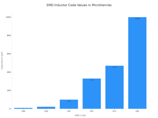
Technicians decode a three-digit numeric code by taking the first two digits as a base number. They multiply this base value by 10 raised to the power of the third digit. This calculation yields the final result in microhenries (µH). For example, a code of '470' evaluates to 47 µH, while '102' equals 1,000 µH.
Code | Base Value | Multiplier Calculation | Result (µH) |
100 | 10 | 10 × 10^0 | 10 µH |
220 | 22 | 22 × 10^0 | 22 µH |
101 | 10 | 10 × 10^1 | 100 µH |
331 | 33 | 33 × 10^1 | 330 µH |
471 | 47 | 47 × 10^1 | 470 µH |
102 | 10 | 10 × 10^2 | 1000 µH |
Precision 4-Digit Marking Systems
High-precision components demand greater numerical accuracy on circuit boards. Manufacturers apply four-digit markings to specify tighter tolerances and exact ratings.
High-Tolerance Value Conversion
Four-digit systems expand upon the basic three-digit rules. The first three characters establish significant figures. The fourth character provides the multiplier power.
Four-Digit Code Examples
An engineer reads a four-digit smd inductor code by maintaining the initial three digits. A code reading "1000" equals 100 µH, because $100 \times 10^0 = 100$. A marking of "1001" signifies 1,000 µH ($100 \times 10^1$). This precision layout allows accurate reading for high-grade smd inductor designs.
The "R" Decimal Point Convention
Inductances under 10 µH require a decimal designation. Numerical codes utilize the letter "R" to represent this decimal point position.
Fractional Microhenry Values
The character "R" acts directly as a decimal point in low-inductance component labels. This format prevents errors from tiny dot markings during automated optical inspection.
Component Marking | Role of 'R' | Resulting Value |
R47 | Replaces leading decimal point | 0.47 µH |
1R0 | Replaces decimal point between digits | 1.0 µH |
4R7 | Replaces decimal point between digits | 4.7 µH |
6R8 | Replaces decimal point between digits | 6.8 µH |
Sub-Microhenry Placement Examples
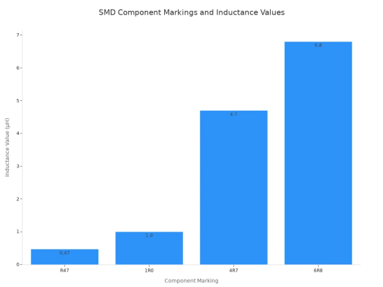
A small smd inductor marked "R47" provides 0.47 µH of inductance. A mid-range smd inductor with "4R7" provides 4.7 µH. Technicians quickly decipher these smd inductor values to confirm correct layout placement. Every inductor on a power supply board plays a critical role. Understanding each inductor marking helps maintain total circuit reliability.
Advanced Alphanumeric Markings and Tolerances
Circuit designers often print extra letters on component casings. These characters indicate strict performance limits and specialized unit systems.
Tolerance Letter Suffixes
Letter suffixes clarify how much an smd inductor deviates from its nominal inductance value. Engineers check these suffix codes to ensure accurate circuit operation.
Standard Letter Tolerances (J, K, M)
Standard tolerance letters appear directly after numerical codes on the component casing. Each upper-case letter represents a specific percentage margin:
Letter Suffix | Tolerance Percentage |
J | ±5% |
K | ±10% |
M | ±20% |
For instance, a technician reads a 10 µH power inductor marked "100K" as having a 10% variance allowance. The actual value of this inductor ranges between 9.0 µH and 11.0 µH.
Tight Tolerance Classifications
High-frequency circuits require precise component behavior. Specialized manufacturers use extra letters like "B" (±0.1 nH), "C" (±0.2 nH), or "D" (±0.5%) for ultra-tight tolerance standards. These tight tolerances protect sensitive filter networks from unexpected frequency shifts.
Nanohenry (nH) Designation Systems
High-frequency applications demand tiny inductance values below the microhenry range. Manufacturers use nanohenry notation systems to mark these miniature parts accurately.
Key Rule: The letter "N" represents both the nanohenry unit and the decimal point position on tiny components.
Using "N" for Decimal Nanohenries
Smaller physical packages cannot fit long decimal numbers on their top surfaces. Designers substitute the letter "N" to indicate decimal points for nanohenry ratings:
· 1N0 = 1.0 nH
· 4N7 = 4.7 nH
· 33N = 33 nH
· R10 = 100 nH (0.10 µH)
Converting Nanohenries to Microhenries
Technicians convert nanohenries to microhenries by dividing the nanohenry value by 1,000. An smd inductor marked "47N" delivers 47 nH of inductance. Converting 47 nH yields 0.047 µH. Understanding these conversion steps helps engineers select the correct smd inductor for high-frequency RF boards.
Cross-Referencing Code Databases
Unusual component labels can confuse technicians during routine board maintenance. Industry databases quickly resolve missing or custom markings.
Using the SMD Codebook
Engineers consult reference tools like the SMD Codebook when physical markings do not match standard numeric rules. These references catalog thousands of surface-mount codes, pinouts, and package styles in organized lookup tables.
Manufacturer Datasheet Lookup
Different vendors sometimes print proprietary markings on a custom smd inductor. Searching official manufacturer datasheets confirms precise smd inductor values, current capacity ratings, and physical package dimensions. Always verify custom component codes before soldering replacement parts onto a live production circuit.
Identifying an Unmarked SMD Inductor
Miniature components often lack printed numerical values on their outer surfaces. Technicians rely on physical traits, board labels, and basic meter tests to identify an unmarked smd inductor.
Physical Package Characteristics
Visual inspection provides immediate clues about component function. Observing surface materials helps workers categorize unknown parts correctly.
Wire-Wound vs Multilayer Construction
Engineers divide components into distinct smd inductor types based on internal structure. Wire-wound designs feature visible copper coils wrapped around a central core. Multilayer designs enclose internal conductor patterns inside ceramic or ferrite bodies. These different smd inductor types serve specific noise filtering or energy storage applications in modern electronics.
Color Differences from MLCCs and Resistors
Component Type | Dominant Casing Color | Surface Appearance |
Surface Mount Inductor | Dark Gray / Charcoal Black | Matte texture, metallic end caps |
Ceramic Capacitor (MLCC) | Light Brown / Tan | Smooth glossy finish |
Chip Resistor | Flat Black | Glossy coating with white top codes |
Technicians distinguish an inductor from a multilayer ceramic capacitor by checking the outer body color. Inductors feature dark gray or black ferrite bodies. Capacitors present yellowish-tan or light brown colors across their outer surfaces.
Quick Multimeter Diagnostics
Basic handheld instruments confirm component identity within seconds. Meter testing separates magnetic parts from capacitors and open circuits.
Measuring Low DC Resistance (DCR)
A technician sets a digital multimeter to measure resistance across component terminals. An inductor exhibits extremely low direct-current resistance (DCR). The meter usually reads values below 5 ohms for standard power parts.
Checking Continuity vs Open Capacitors
Multimeters emit an audible beep during continuity checks on an inductor. The continuous internal wire loop passes low-frequency electrical currents easily. Conversely, an undamaged capacitor blocks direct current and shows an open circuit reading.
Diagnostic Tip: If a component shows near-zero resistance and maintains continuous electrical flow, you are likely measuring an inductor or a ferrite bead rather than a capacitor.
PCB Reference Designators
Printed circuit board silk screen layers offer clear identification labels. Text markings printed directly next to component pads guide technicians during repair work.
Identifying "L" Designators
Designers label board components using standardized alphanumeric prefixes. The letter "L" specifically designates a standard inductor on circuit schematics and silkscreen outlines.
Ferrite Beads vs Power Inductors
Circuit designers distinguish a standard power inductor from high-frequency suppression beads by evaluating circuit labels. The following table illustrates common designator codes found on printed circuit board assemblies:
Component Type | Reference Designator Code |
Inductor | L |
Ferrite Bead | FB, FEB |
Technicians review these designators to select the correct replacement component. Recognizing PCB labels prevents improper installation of ferrite components into power filter paths.
How to Test an SMD Inductor
LCR Meter Setup and Fixtures
Technicians need precise hardware to evaluate tiny component parameters accurately. Specialized equipment prevents external electromagnetic noise from distorting measurements.
Four-Wire Kelvin Test Leads
Four-wire Kelvin connections isolate test lead resistance during measurements. Two leads supply current through the smd inductor, while two independent leads measure potential drop. The primary coil of an inductor requires clean test signals. This four-wire configuration eliminates contact resistance errors on small board components.
Eliminating Stray Parasitics
Test fixtures introduce extra resistance, capacitance, and inductance into measurement loops. Engineers utilize dedicated test equipment to isolate small smd inductor values from background interference:
Equipment / Component Category | Specific Item / Model Examples | Function in Measuring Low SMD Inductance |
Measurement Instrument | Vector Network Analyzer (VNA) like OMICRON Lab Bode 100/500 or Keysight E5061B | Acts as the core high-frequency instrument for 2-port shunt-through impedance characterization. |
Test Fixture | Picotest Component Test Fixture (CTF) | Provides a precision, 2-port measurement interface featuring low-inductance pogo pins to minimize parasitics. |
Calibration & De-embedding | Impedance and 2-Port Calibration Kits, Blank Test Boards | Enables SOL calibration and de-embedding across multiple SMD sizes (0201 through 1210). |
Cabling & Hardware | High-quality PDN cables (BNC-SMA, Molex 4-pin), N/SMA torque wrenches | Ensures reliable, repeatable physical and signal connections with controlled torque. |
Setup Verification | Known DUT Kit (e.g., 1.2 nH Inductor, low-resistance DUTs) | Used for system verification and ensuring accurate picohenry-level measurement confidence. |
Selecting Test Frequencies
Inductance changes across different operating signal frequencies. Technicians configure test equipment to match exact circuit conditions.
Matching Datasheet Parameters
Manufacturers specify standard component values at fixed test frequencies. An inductor exhibits variable magnetic reactance at different energy levels. A test meter must generate the identical excitation frequency listed in component documentation. Matching these parameters yields accurate readings for every tested smd inductor.
Power vs High-Frequency Testing
Power supply inductor components operate under low-frequency conditions between 100 kHz and 3 MHz. Conversely, RF circuits require high-frequency testing near 100 MHz or higher. Each high-frequency inductor behaves differently depending on core construction. Choosing proper test frequencies helps engineers evaluate inductor performance for targeted applications.
Fixture Calibration Procedures
Uncalibrated test leads introduce measurement errors. A precise test setup measures an inductor without offset errors. Calibration removes residual physical characteristics from test fixture leads.
Performing Open Calibration
Technicians follow four structured steps to calibrate fixtures correctly:
1. Set the measurement frequency range and power on the LCR meter to allow internal thermal stabilization.
2. Inspect and clean the test ports and fixture to ensure no physical damage or contamination exists on the dielectric or conductors.
3. Attach the Open standard at the measurement reference plane and execute the Open calibration to measure and store stray capacitance (typically 0.05–0.2 pF).
4. Attach the Short standard at the same reference plane and execute the Short calibration to capture and record residual inductance (typically 0.1–1 nH).
Performing Short Calibration
Executing short calibration zeroes out residual lead inductance. Technicians place a solid copper shorting bar across test fixture contacts. Short calibration protects the small inductor from false impedance measurements. This step establishes a true zero baseline before measuring an individual smd inductor. Proper calibration ensures highly accurate readings for every single inductor.
Advanced Electrical Diagnostics
Engineers perform advanced electrical tests to verify internal components and prevent circuit failure. These procedures evaluate how a magnetic component behaves under real operating loads.
Measuring DC Resistance (DCR)
Technicians measure the direct-current resistance across internal copper windings using specialized meters. Lower resistance values improve total power efficiency inside electronic assemblies.
Detecting Inter-Winding Shorts
Internal wire insulation degrades under severe electrical stress. A short circuit between internal coil loops drastically reduces overall inductance. Technicians compare measured resistance values against smd inductor specifications. A sudden drop in resistance exposes internal winding damage immediately.
Temperature Effects on DCR
Copper wire resistance increases naturally as operating temperatures rise. Engineers calculate thermal resistance shifts to prevent energy losses in power supplies. The following equation predicts resistance changes under thermal stress:
$$\text{DCR}{\text{new}} = \text{DCR}{25} \times [1 + 0.00393 \times (T_{\text{new}} - 25)]$$
High heat increases coil resistance and reduces total system performance over extended operating periods.
Evaluating Quality Factor (Q)
The Quality Factor measures how efficiently an smd inductor stores magnetic energy relative to its internal energy loss. Higher Q values indicate a more efficient component.
Core Loss Assessment
Magnetic cores dissipate energy through hysteresis and eddy currents. Lower core losses maintain strong signal strength across high-frequency circuits. Engineers select high-quality materials to minimize heat generation during daily operation.
High-Frequency Performance
Radio frequency circuits depend heavily on a high Quality Factor. High Q values maintain clear signals across demanding wireless applications.
RF Application Aspect | Operational Role and Importance of High Q |
Energy Efficiency & Loss | Evaluates stored energy against dissipated energy; higher Q minimizes thermal power dissipation in PAs and matching networks. |
Signal Selectivity | Delivers refined filtering capabilities and enhances the suppression of out-of-band signals. |
Phase Noise | Stabilizes resonators to yield purer oscillator outputs with reduced phase noise. |
Receiver Sensitivity | Prevents degradation of low-amplitude, weak RF signals via minimal network loss. |
Bandwidth Control | Governs signal response width (High Q creates narrow bandwidth; Low Q broadens bandwidth). |
Saturation Current and Bias Testing
Direct currents alter magnetic performance in power conversion circuits. Test systems apply direct current bias to evaluate core saturation limits.
Inductance Roll-off Under Load
When an SMD power inductor reaches its DC saturation current ($I_{sat}$), its inductance value experiences a sharp and significant decline. Exceeding the DC saturation current causes several negative operational effects:
· Substantial decrease in the inductor's efficiency
· Inability to store magnetic energy properly
· Increased risk of system performance degradation or complete power supply failure
Ferrite Core Thermal Limits
Excessive current drives ferrite materials past their magnetic saturation points. Overheated magnetic cores lose structural permeability rapidly. Every power inductor requires proper thermal management to avoid overheating. Engineers monitor heat generation to keep each smd inductor within safe operational limits.
How to Choose an SMD Inductor for Your Circuit
Engineers evaluate board demands before picking magnetic parts. Proper component selection prevents voltage drops and thermal issues.
Key Parameters in SMD Inductor Selection
Engineers follow structured steps for smd inductor selection to guarantee stable board performance. Critical smd inductor specifications dictate power behavior under real loads.
Inductance, Isat, and Irms Ratings
Knowing how to choose an smd inductor requires analyzing current thresholds. The saturation current (Isat) marks the point where core limits cause an inductance drop. Conversely, heating current (Irms) defines the continuous current limit causing internal thermal rise.
Parameter | Definition | Selection Guideline |
Saturation Current ($I_{sat}$) | Threshold where core limits lower the inductance value. | Select a rating exceeding peak circuit currents. |
Heating Current ($I_{rms}$) | Continuous DC current causing internal self-heating. | Choose a rating higher than the continuous operating current. |
DC Resistance (DCR) | Winding resistance causing $I^2R$ power loss. | Target lower milliohm values to maximize efficiency. |
A smart smd inductor selection process balances low DC resistance against core loss limits.
Selection Tip: Engineers choose a lower DCR rating to reduce energy loss. However, learning how to choose an smd inductor also involves verifying that $I_{sat}$ comfortably exceeds transient circuit spikes.
Package Footprint and Shielding Options
Designers analyze physical package traits during smd inductor selection. Shielded and unshielded designs offer clear trade-offs:
· Shielded Components: Contain magnetic flux within a closed core. They yield shielding effectiveness above 40 dB and reduce PCB space needs by 30–50%.
· Unshielded Components: Radiate magnetic fields into adjacent areas. They demand dedicated keepout spaces on circuit boards.
Checking dimensions and vertical clearances confirms mechanical fit during standard smd inductor selection.
Matching Components to Application Needs
Different electronic circuits require distinct magnetic properties. Engineers adapt their smd inductor selection approach based on targeted board applications.
Power Supplies vs RF Circuits
Power switching circuits require robust smd inductor designs with high current ratings. RF communication networks prioritize self-resonant frequency (SRF) and high Quality Factor (Q) values instead.
Application Type | Primary Focus | Key Design Requirement |
Power Supplies | Energy storage and power delivery | High $I_{sat}$, high $I_{rms}$, low DCR |
RF Circuits | Signal filtering and resonance | High SRF, high Q factor, tight tolerance |
Engineers explore various smd inductor types to meet these diverse operational goals across high-frequency applications.
Cross-Referencing Replacement Parts
Replacing obsolete components requires extra care. Learning how to choose an smd inductor for repairs involves matching footprint sizes, pad layouts, and thermal limits.
1. Review original datasheet parameters, focusing on $I_{sat}$, $I_{rms}$, and DCR.
2. Confirm footprint dimensions to ensure pad compatibility.
3. Compare candidate parts against the target circuit operating temperature range.
Understanding how to choose an smd inductor protects circuits from noise and component failures across high-density applications.
Technicians master component diagnostics by reading printed codes, verifying physical casing traits, and testing magnetic parameters with calibrated instruments. Rigorous testing discipline requires zeroing out fixture parasitics on LCR meters before measuring any low-value smd inductor. Precise measurements verify DC resistance and confirm inductance ratings under standard operating frequencies. Keeping datasheets accessible simplifies smd inductor selection and guides technicians on how to choose an smd inductor for successful board repairs. A technician replaces a damaged inductor only after matching physical footprints, saturation current limits, and thermal tolerance.
FAQ
How does a technician identify an smd inductor with no printed code?
A technician checks body color and measures low DC resistance to identify an smd inductor. Dark charcoal bodies with near-zero resistance indicate magnetic coils.
Quick Diagnostic Tip: Always verify PCB silkscreen labels. The letter "L" confirms a standard magnetic coil, while "FB" indicates a ferrite bead.
What does the letter "R" mean on a component casing?
The letter "R" represents a decimal point for values below 10 microhenries. A small inductor marked "4R7" provides 4.7 microhenries. This notation format prevents misreading tiny printed decimal dots during automated board assembly.
What happens when an inductor exceeds its saturation current?
When an inductor exceeds its saturation current limit, its inductance drops rapidly. The magnetic core overheats quickly, reducing overall circuit power efficiency and risking immediate voltage instability.
Why do engineers use four-wire Kelvin leads during testing?
Four-wire Kelvin test leads isolate test lead resistance during high-precision measurements. Two leads supply current, while two independent leads measure potential drop. This setup eliminates contact resistance errors on small board parts.
How does an inductor differ from a ferrite bead?
An inductor stores magnetic energy to filter low-frequency signals or regulate output voltage. A ferrite bead dissipates high-frequency noise directly as heat energy. PCB silk screens mark beads with "FB" instead of "L".
What tolerance does the letter "K" represent?
The upper-case letter suffix "K" specifies a ±10% tolerance margin. An inductor marked "100K" ranges between 9.0 and 11.0 microhenries during normal circuit operation.
Why do high-frequency circuits require tight tolerance parts?
A high-frequency inductor demands precise electrical behavior. Tight tolerance ratings protect sensitive filter networks from unexpected frequency shifts, ensuring stable signal transmission across modern wireless applications.