 English
 Vietnamese
 Italian
 Spanish
 Thai
Thai Japanese
 Portuguese
 Korean
 Russian
 French
 German
 Polish
 Indonesian
Practical Guide to Integrating I-Shaped Inductors in Through-Hole Assembly
Engineers integrate an i-shaped inductor into through-hole printed circuit boards to perform energy storage and voltage regulation. This component suppresses noise during filtering tasks. Unlike axial inductors, compact radial inductors save board surface area while managing high current flow. The core geometry concentrates magnetic flux lines, maintaining stable inductance across operating conditions.
Proper assembly requires strict physical control of radial inductors in production. Power circuits depend on accurate footprint design and precise magnetic field isolation to shield nearby traces. Manufacturing guidelines enforce radial lead forming rules to prevent stress on each inductor bobbin. Controlled heating profiles eliminate thermal stress during soldering, ensuring reliable joints for every power supply application and current path.
Key Specifications for I-Shaped Inductor Selection
Selecting the correct i-shaped inductor ensures reliable operation in power circuits. Engineers evaluate electrical specifications to match components with circuit requirements. Unshielded ferrite bobbins deliver high saturation threshold options for compact boards. These radial parts save horizontal surface area compared to traditional axial inductors.
Saturation Current and Core Material Impact
Core materials directly control inductor performance parameters during high power demand. The saturation current specifies the point where the initial inductance value drops by 20 to 30 percent. Exceeding this limit causes core saturation. Saturation increases current ripple and degrades circuit efficiency. Therefore, designers choose a part with a saturation limit higher than the peak circuit current.
Operating frequency also limits effective inductor parameters. Every open core has a self-resonant frequency where parasitic capacitance changes behavior. Engineers operate the component below this threshold to preserve proper inductance. Axial inductors offer similar inductive properties, but vertical bobbin geometries handle magnetic flux density better in tight spaces.
Electrical specification | Design significance for radial I-shaped through-hole power inductors |
Inductance | Sets energy storage and filtering corner frequency; select to satisfy ripple-current or resonant-frequency requirements. |
Saturation current | Current at which inductance drops 20-30%; must exceed peak current to avoid core saturation and excessive ripple. |
Temperature-rise current | Current causing a specified temperature rise (typically 40°C); should be above continuous operating current to prevent overheating. |
DC resistance | Copper-winding resistance causing I²R loss and voltage drop; low DCR improves efficiency in high-current power supplies. |
Self-resonant frequency | Frequency above which parasitic capacitance makes the inductor behave capacitively; operate below SRF to maintain inductance. |
DC Resistance and Thermal Derating Limits
Copper windings create direct current resistance within the component. High resistance converts energy into unwanted heat, producing severe power loss. Selecting low resistance parts minimizes energy loss in high-current circuits. Thermal management relies heavily on these basic inductor specifications during continuous operation.
The temperature-rise current defines continuous current limits. This parameter marks the point causing a standard 40°C temperature rise. Excessive operating thermal stress damages winding insulation over extended periods. Proper inductor selection balances physical dimensions against overall thermal performance. Designers evaluate these inductor characteristics to prevent core overheating. Compared to axial inductors, radial bobbins dissipate excess heat efficiently into ambient air. Proper evaluation of all inductor performance parameters ensures stable circuit operation.
PCB Layout and Magnetic Shielding Rules
Board designers regulate circuit energy paths by placing power inductor components along direct routing channels. An i-shaped inductor performs core energy storage while stabilizing rapid current fluctuations in power supplies. Radial inductors occupy small surface areas, yet their open magnetic structures radiate unshielded flux fields into nearby board layers. Engineers route high current traces directly beneath the bobbin center to maintain stable power loops. Proper routing minimizes loop area, reducing radiation noise and preventing unnecessary power loss across high-frequency switching circuits.
Magnetic Coupling and Component Placement
Open ferrite cores release magnetic flux directly into surrounding circuit board space. This stray flux couples into high-impedance traces, introducing unwanted electromotive force into sensitive signals. Designers place each power inductor far away from analog feedback paths and digital communication lines. Compared to horizontal axial inductors, upright bobbins cast a vertical flux pattern that concentrates field intensity above the board surface. Placing sensitive traces outside this magnetic field preserves signal integrity across every operational application. Board designers isolate power stages to maintain pristine signal paths across complex printed circuit assemblies.
High-current switching paths demand strict spatial isolation from high-frequency signal lines to suppress electromagnetic interference on multi-layer printed circuit boards.
Maintaining clearance prevents field overlap and unwanted mutual inductance between adjacent components. Standard design rules enforce specific physical spacing around open bobbin cores:
· Keep high-frequency signal traces at a minimum distance equal to twice the inductor core diameter.
· Orient neighboring radial inductors at right angles to minimize mutual magnetic coupling.
· Avoid routing sensitive feedback traces directly beneath the active coil winding.
Footprint Design and Hole Clearance
Accurate footprint dimensions ensure mechanical stability and reliable electrical connections during automated assembly. Drill holes must provide proper clearance for component leads to accommodate smooth insertion on the factory floor. Tight lead clearance prevents component tilting, maintaining a consistent vertical magnetic axis. Excessive lead tension causes mechanical stress that alters core properties, changing the target inductance value over prolonged operation. Fabricators verify plated through-hole diameters to ensure adequate solder flow during wave processing.
Proper pad sizing supports heavy ripple current without causing thermal hot spots on copper layers. Larger copper pads dissipate heat and secure the physical package against vibration. Unlike axial inductors, vertical packages concentrate structural weight on two through-hole terminals. Mechanical stress from thermal expansion can crack fragile core material if pads lack adequate solder relief. Engineers calculate trace width using standard copper weight formulas:
minimum trace width = maximum continuous current / (copper thickness x allowable temperature rise factor)
Designers keep ground planes clear of the region directly under the core open gap. Continuous copper beneath unshielded bobbins creates eddy currents, reducing overall circuit inductance. Removing ground copper in this localized area stabilizes the expected inductance value and preserves nominal inductance under load. In addition, keeping high current power traces wide lowers electrical resistance, allowing the passive inductor to maintain stable inductance without generating excess heat. Final mechanical inspection confirms that vertical radial inductors sit flush against the board surface without applying torque to lead wires. Careful footprint execution protects fragile ferrite bobbins from mechanical strain while sustaining peak current performance.
Radial Lead Forming and Mounting Practices
Lead Bending Techniques and Stress Relief
Assembly lines prepare wire leads before placing an open inductor onto printed circuit boards. Proper lead bending prevents physical fractures on delicate magnetic cores. Technicians pre-form wire terminals to align component leads with printed circuit board insertion holes. Direct bending near the bobbin base creates severe mechanical stress, cracking fragile ceramic inductor materials instantly. Therefore, operators clamp the lead wire firm near the component body during bending operations. Clamping tools absorb mechanical force and isolate the ceramic body from dangerous bending tension.
Manual forming tool jaws support lead wire bases securely during lead preparation. Automated machines use custom die sets to shape both terminals simultaneously. Unlike axial inductors, upright parts require precise symmetrical bends to maintain vertical alignment. Forming tools maintain a minimum bend radius equal to two times the wire diameter. This specific radius prevents copper wire necking and protects terminal plating integrity. In addition, technicians create a small stress relief loop in each wire lead. This loop absorbs physical expansion during thermal cycling, preserving stable nominal inductance over time. Controlled bending forces also reduce internal copper wire fatigue during high-volume manufacturing assembly.
Mounting Heights and Vibration Securing
Mechanical stability dictates long-term electrical performance in harsh operating environments. Unsecured vertical components experience high physical momentum under mechanical shock. Excessive component movement causes lead fatigue and fracture over extended operational periods. Unlike horizontal axial inductors, vertical power inductor components require dedicated physical support structures. Technicians install mechanical standoffs beneath bobbin bases to maintain proper elevation above circuit board surfaces.
IPC-A-610 standards require specific standoff clearances to allow complete solder fillet formation and thorough cleaning solvent flow beneath raised components.
Assembly processes define precise mechanical positioning and bonding rules for through-hole parts:
1. Set component standoff height between 0.5 millimeters and 1.5 millimeters above the printed circuit board surface.
2. Apply a non-conductive silicone adhesive dot to secure the component body against heavy mechanical vibration.
3. Allow structural adhesives to cure completely before running circuit boards through high-temperature wave soldering machines.
Proper mounting techniques protect delicate power circuits in high-vibration power supply application settings. Radial inductors remain upright and stable during severe shock tests when adhesives secure component bases. In contrast, heavy axial inductors can pull away from solder pads under lateral acceleration. Stiff mechanical mountings eliminate copper trace strain under heavy ripple current conditions. Correct mounting height prevents direct thermal contact between bobbin cores and hot current paths. These protective steps maintain design inductance values across high-temperature operational cycles. Solid adhesive anchors also reduce acoustic noise caused by magnetostrictive core movement under pulsating current.
Radial inductors deliver superior packing density on crowded circuit boards. Engineers specify radial inductors when boards lack horizontal space for long components. Furthermore, radial inductors dissipate heat effectively through open air channels. Proper lead forming ensures that radial inductors fit smoothly into through-hole patterns without mechanical binding. Unlike elongated axial inductors, compact upright units manage peak current efficiently in every industrial application. Reliable mechanical mounting allows an i-shaped inductor to withstand severe industrial conditions. A well-mounted power inductor operates reliably without solder joint degradation. Strict assembly standards prevent production defects.
Wave Soldering Protocols for Inductor Assembly
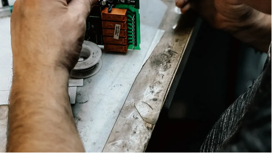
Thermal Shock Avoidance in Preheating
Wave soldering machines pass through-hole circuit assemblies over molten solder waves to create permanent physical joints. High thermal changes create severe stress inside ferrite cores during this automated process. Technicians apply a gradual preheating stage to elevate board temperatures steadily. Proper ramp rates prevent physical cracking in brittle ceramic core structures. Gradual preheating also drives off volatile solvents from flux chemistry before direct contact with molten solder. A through-hole inductor requires precise thermal management to survive rapid wave immersion.
Engineers maintain specific preheating temperature profiles to protect radial inductors on the production line. A preheat ramp rate between 2°C and 4°C per second prevents core fractures. Unshielded component bodies expand uniformly when heat rises gradually along the conveyer path. Uneven thermal expansion generates internal stress, causing sudden magnetic loss within core structures. Controlled preheating keeps core performance stable during heavy peak current exposure in each high-density power application.
Manual Soldering and Quality Inspection
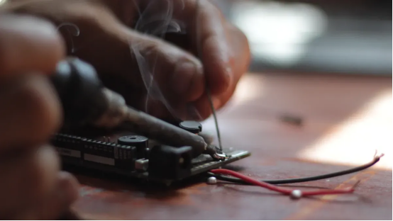
Technicians perform manual soldering operations for specialized low-volume boards or rework tasks. Operators adjust iron tip temperatures according to board thickness and terminal lead mass. Excessive tip temperatures transfer excess thermal energy into thin copper coils rapidly. Rapid heating damages wire insulation, creating short circuits across internal turns. This insulation breakdown changes total inductance unexpectedly during high operating current conditions. A damaged inductor degrades efficiency across the entire power stage.
Quality inspectors check solder fillets according to IPC-A-610 standards to guarantee joint integrity. Complete solder flow must fill every plated through-hole completely to handle heavy continuous current. A defective solder joint increases electrical resistance across high current paths. Inspectors verify that an open-core power inductor sits upright without applying torque to delicate lead terminals. Operators take special care when handling radial inductors in demanding power designs to keep the coil intact.
Quality control teams follow a strict evaluation process during final testing:
1. Inspect solder fillets under magnification to confirm complete 360-degree wetting around lead wires.
2. Measure nominal inductance using an LCR meter to detect hidden core fractures or shorted windings.
3. Check component spacing to ensure stable ripple current flow without shorting neighboring traces.
4. Verify target inductance and rated saturation current limits to ensure full functional performance.
Troubleshooting Core and Joint Failures
Ferrite Cracking and Joint Fractures
Mechanical shock and excessive solder heat crack brittle ferrite core bodies during manufacturing. Physical impact breaks the rigid ceramic structure. Cracks create artificial air gaps inside the magnetic flux path. These internal micro-gaps lower the baseline inductance value dramatically during preliminary circuit testing. Cracked bobbin bases also concentrate physical strain onto component lead wires during continuous mechanical vibration. Unsecured components wobble, widening core fractures and degrading magnetic performance over extended operation.
Rapid temperature swings trigger solder joint fractures around through-hole termination pins. Thermal shock during wave processing stresses solder fillets. High continuous current creates localized thermal expansion across thin copper pads. Microscopic solder cracks increase electrical contact resistance, causing localized heat loss across the printed circuit board. Technicians inspect fractured joints using optical magnification tools according to IPC-A-610 inspection standards. Re-soldering damaged pins stabilizes electrical connections without overheating nearby component structures.
Inductance Shift and Shorted Winding Detection
Overheated copper coil turns break down thin enamel insulation layers over time. Thermal overload melts the protective coating, creating direct electrical contacts between adjacent wire loops. Shorted turns eliminate active coil loops and alter the expected inductance value rapidly. An LCR meter measures total inductance across operational test frequencies to identify internal short circuits. Test operators compare each measured reading against the specified inductance value to flag damaged parts immediately.
High peak current stress shifts core magnetic properties over extended operational lifespans. Heavy electrical loads saturate open ferrite structures, altering baseline core permeability. A severe core shift reduces total inductance and lowers the continuous current handling capability of power stages. Excessive ripple current causes unexpected core saturation, driving further current spikes through sensitive circuit paths. Testing a suspect power inductor under real operational loads verifies true magnetic performance.
This comprehensive evaluation confirms the actual inductance value before final circuit board delivery. A healthy radial inductor maintains stable inductance during continuous power delivery. Replacing a degraded inductor restores the target inductance value across all operating conditions. Proper diagnostic testing keeps each power inductor cool under heavy current demand.
Successful integration of an i-shaped inductor requires strict adherence to physical rules. Engineers match component specifications to circuit needs. Radial inductors demand controlled lead forming, safe placement clearance, and gentle preheating to manage continuous current. Verifying critical inductor parameters prevents thermal shock during wave soldering, ensuring each through-hole inductor operates reliably.
Engineers validate pre-production prototypes using a step-by-step verification process before initiating high-volume wave soldering assembly runs:
1. Inspect lead bends to confirm mechanical stress relief on radial inductors.
2. Verify solder fillet integrity to support peak current flow.
3. Measure post-assembly inductance using an LCR meter, comparing the measured inductance value against baseline inductance to confirm target inductance.
FAQ
How do radial inductors compare to axial inductors on crowded boards?
Radial inductors save horizontal surface area on compact circuit assemblies. Vertical bobbins dissipate heat efficiently into ambient air. In contrast, axial inductors require larger horizontal footprints. Engineers choose radial inductors over axial inductors to manage continuous current in tight power supply spaces.
Why do technicians preheat a power inductor before wave soldering?
Gradual preheating prevents thermal shock inside fragile ferrite structures. Rapid temperature swings create internal mechanical stress, cracking ceramic core bodies. Maintaining a preheat ramp rate between 2°C and 4°C per second protects components during automated soldering.
How do operators detect a damaged coil or incorrect inductance value?
Operators measure electrical properties with an LCR meter. Overheated wire turns break down protective insulation, creating internal short circuits. Shorted loops reduce overall circuit inductance. Diagnostic testing confirms whether the physical coil retains its target inductance value under real test conditions.
What physical factors cause a permanent shift in baseline inductance?
Mechanical shock cracks brittle ferrite core bodies, introducing artificial air gaps. These micro-gaps lower baseline inductance significantly. High continuous current saturation or excessive heat shock also alters core permeability, degrading overall inductance during extended power delivery cycles.