 English
 Vietnamese
 Italian
 Spanish
 Thai
Thai Japanese
 Portuguese
 Korean
 Russian
 French
 German
 Polish
 Indonesian
How to Choose Between Common Mode and Differential Mode Noise Filters
When a circuit experiences unwanted noise, engineers must choose the correct filter. The decision depends on the noise type: common mode or differential mode. Common mode noise appears identically on both lines relative to ground. Differential mode noise appears as a voltage difference between the two lines. A helpful analogy is a two-lane highway. Common mode resembles both lanes moving in the same direction relative to the shoulder. Differential mode resembles traffic moving in opposite directions. Proper Noise Filter Selection begins with identifying which noise type is present. That identification leads to the right filter solution. Making a wrong Noise Filter Selection can worsen the noise problem or leave it unresolved. Therefore, understanding these two noise types is essential for effective circuit design.
Common Mode vs. Differential Mode Noise
Defining Common Mode Noise
Common mode noise appears as identical voltage fluctuations on both signal lines relative to a common ground. This noise type shares the same phase and amplitude on both conductors. External electromagnetic interference and ground loops generate most common mode noise.
The sidewalk analogy illustrates common mode noise clearly. Two people walking side-by-side in the same direction on a sidewalk represent the two signal lines. The ground serves as the sidewalk itself. When both people move together relative to the sidewalk, they mirror common mode noise behavior. Both lines carry the same unwanted signal relative to ground.
Differential signaling relies on common mode rejection to maintain signal integrity. When two wires route closely together as a differential pair, external EMI induces nearly identical noise voltages on both lines. The receiver subtracts one signal from the other, canceling the identical noise components. This cancellation preserves the original voltage difference. Common mode noise becomes problematic when it exceeds the receiver's CMRR capability. CMRR values range from 40 to 60 dB, attenuating noise by 100 to 1000 times.
Trace asymmetry reduces rejection effectiveness. For a 10 Gbps signal with a 100 ps bit period, the maximum allowable skew is approximately 10 ps. A trace length mismatch of about 2 mm on FR-4 material produces this skew. This mismatch converts common mode noise into differential noise, degrading signal integrity.
Ground loops create another significant common mode noise source. In industrial data acquisition systems, connecting multiple sensor terminals, analog input commons, and shield grounds to the same power supply negative creates multiple conductive paths between ground points. This configuration allows circulating currents from AC mains ground potential differences to couple into the signal ground. The result manifests as a varying voltage offset between ground points. Engineers observe approximately 1 mA peak-to-peak noise on 4-20 mA signals and roughly 50 mV peak-to-peak noise on 0-5 V sensor outputs from ground loop coupling. Proper grounding techniques prevent these loops from forming.
A ground loop occurs when there are multiple conductive paths between two points in a grounding system. Tying the commons of two physically separate power supplies together creates a large conductive loop. This loop acts like an antenna, picking up electrical noise from the industrial environment. This current flowing in the common rail creates a varying voltage offset between different ground points in the system.
Defining Differential Mode Noise
Differential mode noise exists as a voltage difference between the two signal lines. This noise type appears across the lines rather than between each line and ground. Switching currents within the circuit itself generate most differential mode noise.
The two people walking towards each other on the same path provides a clear analogy. When the individuals move in opposite directions, their relative motion creates a difference between them. Similarly, differential mode noise creates a measurable voltage difference between the two conductors.
DC-DC converters generate significant differential mode noise. The following table summarizes typical characteristics:
Parameter | Value |
DM dominance frequency range | Below 500 kHz, gradually decreasing by 2 MHz |
Example converter | 1 MHz GaN DC-DC converter (EPC 9101) |
DM reduction with 100 µH series inductor | 10 to 18 dB across the frequency range |
DM reduction with external filter board | Almost complete reduction |
A 100 µH series inductor provides 10 to 18 dB of noise reduction. An external filter board with proper design achieves almost complete reduction. Understanding these frequency characteristics helps engineers select the appropriate filtering components. Engineers designing filters for these converters must address this frequency range to achieve effective noise suppression.
How Common Mode Chokes Work
Bifilar Winding and Field Cancellation
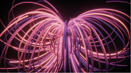
A common mode choke uses two coils wound side by side on a single magnetic core. This construction is called bifilar winding. The two windings carry the same number of turns and share the same core material. The core material determines the choke's frequency performance. Ferrite cores block high-frequency noise effectively but operate within a narrower frequency range. Powdered metal cores handle wider frequency ranges but may store more energy, which can lead to heat generation or inductance loss. Any core material must withstand repeated current fluctuations without overheating or losing inductance.
The bifilar arrangement creates a remarkable magnetic behavior. For differential mode signals, the desired currents flow in opposite directions through the two windings. These opposing currents generate magnetic fields that cancel each other completely. The net flux in the core remains near zero. This cancellation produces ultra-low DC resistance, allowing the desired signal to pass with minimal loss. For common mode noise, the currents flow in the same direction through both windings. The magnetic fields reinforce each other, creating a strong flux in the core. This reinforced field generates high impedance that blocks the noise.
Core principle: For differential signals, desired currents flow in opposite directions, causing their magnetic fields to cancel each other out, which allows the signal to flow freely without distortion. In contrast, common mode noise currents flow in the same direction, reinforcing their fields and creating high resistance that chokes the noise.
High Impedance to Noise, Low to Signal
The impedance behavior of a common mode choke depends entirely on the current direction. The table below summarizes this relationship:
Current Type | Magnetic Field Behavior | Resulting Impedance |
Differential (desired signal) | Equal and opposite currents → fields cancel (net zero flux) | Very low inductance (only leakage) → signal passes freely |
Common mode (noise) | Equal and same-direction currents → fields add (high flux) | High impedance (Z=ωLCM) → noise is blocked |
The bifilar winding intentionally minimizes leakage inductance. The side-by-side placement of the windings reduces stray fields. This low leakage inductance results in low differential-mode impedance. This design choice proves critical for data-line chokes. It allows differential mode signals to pass with minimal impedance, preserving signal integrity by avoiding degradation of rise times and preventing jitter. Sectional winding, in contrast, increases leakage inductance for differential-mode attenuation in mains filters, but bifilar chokes do not serve this purpose.
This targeted suppression makes common mode chokes ideal for differential pairs and power lines. The choke filters only the unwanted common mode noise while leaving the desired differential signal untouched. Engineers can place these components in series with signal lines without worrying about distorting the data they carry.
How Differential Mode Inductors Work
Single Coil and Series Impedance
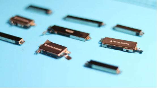
A differential mode inductor uses a single coil wound on a magnetic core. The inductor places in series with the power line. This construction presents impedance to all high-frequency currents. Both differential mode noise and common mode noise experience some attenuation. The impedance increases with frequency.
Saturation current determines the practical operating limit.
Saturation current (I_sat) impact on filtering: When the operating current exceeds the saturation threshold, the core saturates, causing a sharp drop in inductance. This inductance collapse directly degrades the differential mode inductor's ability to attenuate noise. Therefore, the saturation current must be selected to exceed the circuit's peak current to maintain stable filtering performance.
The self-resonant frequency places an upper limit on effective filtering.
A 10 mH common-mode choke exhibits a self-resonant frequency (SRF) at 200 kHz. Above this frequency, the choke behaves like a capacitor, not an inductor. When designing filters for noise above 1 MHz, the inductor's frequency characteristics must be carefully considered, as the component's inductive behavior is lost beyond its SRF, rendering it ineffective for filtering high-frequency switching noise.
The SRF depends on inter-winding capacitance, typically 0.5 to 5 pF. This capacitance forms a parallel resonant circuit with the inductance. Above the SRF, the impedance becomes capacitive. The SRF must exceed the operating frequency by at least three times. A filter for 100 MHz requires inductors with SRF above 300 MHz.
Filtering Line Ripple and Switching Noise
A differential mode inductor serves as a general-purpose filter. It can filter some common mode noise, but its primary purpose involves blocking differential mode ripple current and switching noise. DC-DC converters generate significant ripple current.
The ripple current reduction represents a design choice.
· Typical ripple current is chosen as 20–40% of the average output current.
· A common starting point is 30%, expressed as ΔIL = 0.3 × IL.
· This range is a design guideline, not a fixed physical limit.
A standard design target is 30% ripple current. For a 5 A output, this means ΔIL = 0.3 × 5 A = 1.5 A. Reducing ripple further improves output quality but requires a larger inductor. Increasing ripple reduces inductance but raises peak current stress. The 30% value provides a balanced default.
The inductor must handle peak current without saturating. Peak current equals the average output current plus half the ripple current. For a 5 A output with 30% ripple, peak current reaches 5.75 A. The saturation current rating must exceed this value.
Noise Filter Selection: Key Parameters
Identifying Your Noise Source
The first step in any Noise Filter Selection process requires identifying the noise type. Engineers measure the noise between the two signal lines and between each line and ground. A spectrum analyzer provides the most effective tool for this characterization.
The operator follows a systematic procedure. First, characterize the interference by measuring the center frequency, bandwidth, amplitude, temporal behavior, and modulation characteristics. Next, classify the noise source. A continuous wave signal at a round frequency suggests an oscillator or clock. A signal with sidebands at the power line frequency indicates power line-related noise. A broad hump of noise suggests broadband interference from switching power supplies or LED drivers. Finally, use near-field probes to sniff for the signal near suspected sources such as power supplies, digital circuits, or cables. The signal will be strongest at the source itself.
The resolution bandwidth adjustment proves critical. Start with a wide resolution bandwidth for a quick overview. Once a suspicious signal appears, narrow the resolution bandwidth to resolve closely spaced signals. For very narrowband signals such as oscillator leakage or CW spurs, use the narrowest resolution bandwidth available to measure the exact frequency.
A differential probe measures the voltage difference between two points without requiring a ground reference. This probe rejects common-mode signals, which makes it highly effective for capturing low-level signals in noisy environments. To verify the probe's common mode rejection, the operator shorts the differential inputs and connects both probe tips to the same point in the circuit. Dividing the amplitude of the test probe output by the amplitude of the input signal yields the CMRR. Repeating this experiment at several frequencies on the CMRR plot verifies performance across the frequency range.
If the noise appears identically on both lines relative to ground, the noise type is common mode. If the noise appears as a voltage difference between the two lines, the noise type is differential mode. This distinction determines the correct filter choice.
Evaluating Impedance, Current, and Size
For common mode chokes, the impedance at the specific noise frequency determines filtering effectiveness. The impedance must be sufficiently high at the target noise frequency. The self-resonant frequency must exceed the highest noise frequency of interest.
The rated current must handle continuous operation without thermal runaway. The continuous RMS current must be within the rated current for the application. The temperature rise must remain within limits to ensure inductance stability.
Saturation current must be selected to exceed the circuit's peak current to maintain stable filtering performance. The operating current should not exceed the rated current for continuous operation, and derating may be necessary at elevated temperatures.
The DC resistance determines power loss. The I²R loss equals the RMS current squared multiplied by the DCR. The leakage inductance varies between designs and sometimes acts as a differential mode filter. Engineers must control this parameter carefully.
For differential inductors, the saturation current and DC resistance form the primary selection criteria. The inductor must not saturate at the peak current. The DCR must remain low enough to minimize power loss and heat generation.
Package size and cost complete the Noise Filter Selection. Surface mount devices suit compact PCB layouts. Through-hole toroidal designs offer different trade-offs. The core material choice between ferrite and powdered metal affects both cost and performance. Higher current requires larger wire gauge, which reduces the number of turns and lowers the impedance. Optimized winding techniques can improve copper fill factor for high-current designs. The Noise Filter Selection process must balance all these parameters against the application constraints.
Selecting the right filter becomes straightforward with a clear process. Engineers must first identify the noise type. They measure whether noise appears between the lines or between each line and ground. This single measurement determines the entire Noise Filter Selection path.
A simple checklist guides the decision:
1. Measure the noise between lines and between each line and ground.
2. Choose a common mode choke for identical noise on both lines relative to ground.
3. Choose a differential mode inductor for noise appearing as a voltage difference between lines.
4. Verify impedance at the noise frequency, current rating, and physical size.
Understanding these two noise types transforms a complex choice into a logical decision. Engineers who master this distinction select effective filters with confidence.
FAQ
Can a common mode choke also filter differential mode noise?
A common mode choke provides minimal differential mode filtering through its leakage inductance. This stray inductance varies between designs and remains intentionally low in bifilar wound chokes. For substantial differential mode attenuation, engineers should pair a common mode choke with a separate differential mode inductor rather than relying on leakage alone.
What happens if the wrong filter type is installed?
Installing a differential mode inductor for a common mode noise problem leaves the noise largely unaddressed. The inductor presents some impedance to common mode currents, but its single coil design lacks the field reinforcement mechanism that makes common mode chokes effective. The noise persists, and the circuit continues to experience interference.
How does saturation affect filter performance?
When current exceeds the saturation threshold, the core loses its magnetic properties. Inductance drops sharply, and the filter stops attenuating noise effectively. Engineers must select components with saturation current ratings exceeding the circuit's peak operating current.
Do filter selections differ for power lines versus data lines?
Yes. Power line filters must handle continuous high currents and prioritize saturation current and thermal performance. Data line filters focus on preserving signal integrity, requiring minimal differential mode impedance to avoid distorting waveforms. Common mode chokes serve both applications, but the selection criteria emphasize different parameters depending on the installation context.
Can multiple filters be combined for better performance?
Engineers often combine both filter types in a single design. A common mode choke paired with differential mode inductors creates a comprehensive filtering solution. This approach addresses both noise types simultaneously. The Noise Filter Selection process should evaluate the combined impedance characteristics to ensure the filters work together without unintended interactions.