 English
 Vietnamese
 Italian
 Spanish
 Thai
Thai Japanese
 Portuguese
 Korean
 Russian
 French
 German
 Polish
 Indonesian
Fix Messy Electrical Noise with a Common Mode Inductor
Common mode electrical noise heavily disrupts CAN bus communication systems inside modern vehicles. Fast switching circuits, electric motors, and high-frequency inverter operations generate severe electromagnetic interference across automotive wiring harnesses. This high-frequency noise creates signal errors and corrupts critical data transmissions. Transceiver-level hardware filtering provides an essential layer of defense against these operational disturbances. Placing a common mode inductor directly onto the physical bus lines eliminates common mode noise effectively while preserving vital differential data signals intact. Proper noise suppression allows automotive design engineers to achieve stable data rates across complex electronic control networks. Reliable filtering also helps designs satisfy strict automotive EMC standards like CISPR 25.
Understanding Automotive CAN Bus Noise

Sources of Noise in Vehicles
Modern automobiles contain numerous electrical noise sources that threaten electronic control units. Electric motors generate high-frequency electromagnetic noise from 2 kHz to 20 kHz within motor windings and power electronics components. These vehicle motor systems also produce audible acoustic noise oscillations between 1 kHz to 20 kHz. Power inverters perform rapid switching operations, creating severe electromagnetic interference. Extended high-voltage cables function like antennas and broadcast this high-frequency interference along harness routes. Furthermore, tight physical layouts force power cables into close proximity with low-voltage signal lines, triggering inductive and capacitive crosstalk. Rapid current fluctuations trigger common mode noise throughout the vehicle harness network.
Multiple factors cause severe ground potential shifts between interconnected automotive nodes.
Cause Category | Key Triggers / Factors | Impact on Ground Potential |
Physical Grounding Defects | Loose ground bolts, terminal corrosion, paint under grounding connections, damaged connectors | Degrades chassis connection, elevating ground resistance |
Electrical & Environmental Load | Hydraulic valve switching, hydraulic pump operation, engine startup, alternator charging | Induces severe electromagnetic interference and sudden voltage fluctuations |
Wiring & Topology Factors | Extended harness lengths, improper shield grounding at both ends | Increases baseline ground resistance and causes unwanted inter-device current flow |
Impact on CAN Signal Integrity
Common mode noise directly damages the signal integrity of Controller Area Network buses. CAN transceivers rely on differential signaling, determining logic states by measuring the voltage differential between CAN High and CAN Low wires. Severe common mode noise shifts the baseline voltage on both signal conductors simultaneously.
High-voltage transients and high-frequency noise drive differential transceivers outside their optimal common-mode operating range. Receiver circuits struggle to reject heavy common mode interference, causing severe signal distortion and timing jitter. Corrupted waveforms alter critical edge transitions and create bit errors inside digital communication packets.
Packet corruption forces CAN controllers to retransmit damaged messages repeatedly. Frequent retransmissions waste precious bus bandwidth, increase latency, and trigger node error counters. Affected electronic control units enter error-passive states or bus-off conditions, completely halting vehicle data transmission.
Filtering Noise with a Common Mode Inductor
Automotive hardware engineers insert passive components into transceiver interface circuits to protect electronic control modules from severe electrical disturbances. A common mode inductor serves as an essential filter placed directly between physical bus wiring connections and transceiver integrated circuits. This hardware placement establishes an effective defense barrier against harsh electromagnetic interference.
Magnetic Flux Cancellation
The core operating principle of this passive component relies on electromagnetic induction across coupled copper wire windings. Inside a common mode choke, the physical setup features two insulated copper wire coils wrapped around a shared magnetic core. When differential signals travel through these coils in opposing directions, the resulting magnetic fields counteract and neutralize one another, enabling the desired signal to travel through freely with minimal interference or loss. Differential CAN bus messages push electric current forward through one wire coil while pulling equal current back through the second wire coil. These opposing equal currents create equal and opposite magnetic fluxes inside the shared magnetic core. The opposing magnetic forces cancel each other out completely. Consequently, the component presents virtually zero inductive impedance to normal differential signal communications.
Common mode electrical noise operates through a completely different physical mechanism across communication wires. High-frequency electrical interference pushes unwanted noise currents in the exact same direction down both signal conductors simultaneously. When common mode noise currents enter the two windings in parallel, the resulting currents generate additive magnetic fluxes inside the ferrite core. These aligned magnetic fluxes reinforce one another instead of canceling out. The additive magnetic field creates high inductive reactance across both signal lines. The magnetic core effectively blocks common mode noise currents while preserving differential data transmission.
High Impedance Noise Blocking
High common mode impedance stops high-frequency noise currents before electrical interference reaches delicate transceiver circuits. Common mode noise currents attempt to travel from signal lines into chassis ground through parasitic capacitance pathways. The inductive choke acts like an electrical wall for high-frequency common mode energy, presenting high impedance specifically to line-to-ground noise paths.
Engineers evaluate component performance parameters when selecting physical filters for electronic systems.
Filter Parameter | Operating Characteristic | Functional Impact on Bus Performance |
Common Mode Impedance | High resistance at target noise frequencies | Attenuates incoming line-to-ground noise spikes |
Differential Impedance | Extremely low resistance across data frequencies | Preserves clean logic signal transitions |
Core Saturation Current | Maximum current rating before inductance drops | Prevents filter performance degradation during transients |
Presenting high impedance to line-to-ground noise enables automotive nodes to pass radiated emission and immunity tests. Vehicle testing protocols require electronic modules to meet strict noise threshold limits without emitting harmful radio frequency interference. The choke blocks high-frequency noise currents from flowing outward into extended vehicle wiring harnesses. Long wiring harnesses act like physical antennas when unblocked noise flows through signal wires. Suppressing common mode currents keeps radiated emissions low and protects surrounding vehicle electronic receivers. High impedance filtering also boosts node immunity against incoming electromagnetic noise bursts from external interference sources. Automotive designs maintain clean signal waveforms and reliable data execution through robust high-frequency noise blocking.
Benefits in Automotive CAN Applications

Inserting specialized choke components into CAN networks provides strong protection for electronic control units. Vehicle networks require constant protection against high-frequency electromagnetic field disruptions. Hardware filters maintain continuous node operation across changing operational environments.
EMI Suppression and Immunity
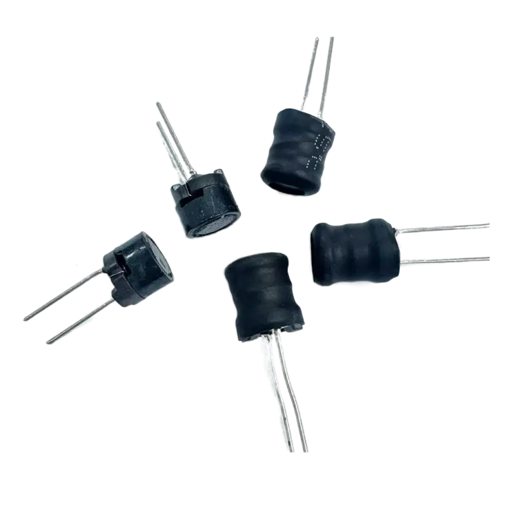
A common mode inductor functions as a dual-coil passive filtering component built around a shared magnetic core. This component mitigates electromagnetic interference by attenuating unwanted noise signals shared across both transmission lines while offering minimal impedance to the differential signals required for clear communication. Modern high-speed CAN FD networks require exceptional signal integrity at high transmission speeds.
Robust physical construction allows these filtering components to endure harsh under-hood automotive environments:
· Noise Suppression and Signal Integrity: Delivers high-efficiency suppression of common-mode noise while safeguarding data integrity for CAN FD communications operating above 10 Mbit/s.
· Standards and EMC Compliance: Adheres to international standards such as IEC 62228-3 and CiA 110, enabling automotive systems to satisfy rigorous OEM EMC requirements.
· Environmental and Mechanical Durability: Built with a wire-wound structure and high-sided metallization to maintain stable electrical operation under continuous vibration and extreme temperature conditions up to +150°C.
Superior electromagnetic immunity prevents external transient voltage spikes from corrupting active differential data streams. Clean differential signals reduce receiver bit error rates across sensitive control channels. Vehicle electronic control modules process data packets reliably without suffering hardware lockups.
Ground Offset Mitigation
Engine operations and high-current load switching alter local reference potentials between distant vehicle electronic nodes. Physical ground potential shifts generate high common mode voltages across the connecting wires. These voltage imbalances threaten transceiver circuits by forcing signal voltages beyond standard input operating ranges.
Filtering hardware absorbs transient common mode energy before voltage spikes enter sensitive semiconductor pins. The magnetic core converts high-frequency energy spikes into localized magnetic fields. High inductive impedance blocks parasitic noise currents from completing paths through chassis ground connections.
Preventing voltage shifts keeps transceiver operating voltages within safe operational windows. Nodes maintain accurate differential voltage measurements despite ground offsets across long wiring harnesses. This stability prevents communication interruptions between critical safety controllers during sudden electrical load swings.
CISPR 25 EMC Compliance
Vehicle manufacturers mandate strict compliance with CISPR 25 electromagnetic compatibility limits. CISPR 25 defines allowable conductive and radiated emission levels for electronic modules placed inside automobiles. Unfiltered CAN wires conduct high-frequency switching noise directly into extended wiring harnesses. Long harnesses act like physical antennas and radiate broad electromagnetic interference across radio frequency bands.
Targeted choke filtering suppresses common mode currents at the physical circuit board interface. Attenuating high-frequency noise currents before signal energy reaches the harness reduces radiated RF emissions significantly. Electronic control modules easily clear CISPR 25 Class 5 emission thresholds when equipped with properly matched filtering components.
Early integration of filtering components simplifies final automotive EMC qualification testing. Design teams avoid costly circuit board redesigns during final vehicle testing cycles. Module housing designs require less physical metal shielding, reducing overall production weight and component manufacturing costs across vehicle production lines. Clean signals ensure smooth integration into complex vehicle electrical architectures.
Selecting the Right Common Mode Inductor
Impedance and Cutoff Frequency
Engineers select common mode chokes based on targeted impedance profiles at specific interference frequencies. A common mode inductor provides maximum attenuation when its peak impedance aligns with system noise frequencies. Design teams evaluate the cutoff frequency to protect differential data signals. Choosing a filter with an excessively low cutoff frequency inadvertently degrades signal transitions.
Proper choke selection balances noise suppression against data rate requirements. CAN FD networks operate at high data speeds, requiring careful frequency response matching. Hardware designers choose components that present high impedance to common mode noise while maintaining low insertion loss for differential messages.
Parasitic Capacitance Control
Internal winding geometry creates unwanted stray capacitance inside passive magnetic components. High parasitic capacitance provides an unintended alternative path for high-frequency electrical signals. This stray capacitance reduces the self-resonant frequency of the component and degrades high-frequency filtering performance.
For Controller Area Network (CAN) applications, common mode chokes should maintain a parasitic winding capacitance below 10 pF to prevent limiting the self-resonant frequency and signal bandwidth. Controlling winding symmetry minimizes differential-to-common mode signal conversion. Precise manufacturing techniques ensure low capacitive coupling across adjacent wire windings.
AEC-Q200 and Current Ratings
Automotive applications demand components certified under strict industry stress qualifications. Passive components must pass rigorous testing protocols specified by the AEC-Q200 standard before installation in vehicles.
Test Category | Specific Stress Test Required |
Environmental Stress | High Temperature Exposure (Storage) |
Environmental Stress | Temperature Cycling |
Environmental Stress | Humidity Bias |
Environmental Stress | High Temperature Operating Life |
Environmental Stress | Resistance to Soldering Heat |
Mechanical Stress | Mechanical Shock |
Mechanical Stress | Vibration |
Mechanical Stress | Board Flex (SMD) |
Mechanical Stress | Terminal Strength (for THT and SMD) |
DC resistance ratings determine component power dissipation during operation. High current loads increase copper winding temperatures inside the ferrite core. Circuit designers select components with sufficient thermal margins to avoid core saturation during prolonged high-temperature operational cycles.
Integrating a common mode inductor guarantees clean signal transmission across high-speed automotive CAN bus networks. This essential passive filtering component delivers a vital dual benefit for modern electronic control systems. The device protects delicate differential data signals while simultaneously blocking high-frequency motor interference and transient ground offsets. Internal ferrite cores suppress destructive noise currents before electrical disturbances reach sensitive transceiver circuits. Hardware engineers must specify AEC-Q200 qualified components during initial circuit layout and schematic design phases. Selecting robust filtering hardware early prevents expensive physical printed circuit board redesigns. Proper component selection allows electronic control modules to pass rigorous CISPR 25 EMC compliance tests smoothly.
FAQ
How does a common mode inductor protect CAN bus signals?
A common mode inductor suppresses high-frequency noise traveling in the same direction on both signal lines. The magnetic core creates high impedance against common mode interference. Meanwhile, equal and opposite magnetic fluxes cancel out for differential data signals, allowing valid messages to pass without distortion.
Why do CAN FD networks require low parasitic winding capacitance?
High parasitic capacitance creates an unintended path for high-frequency energy. This stray capacitance lowers the self-resonant frequency of the choke and degrades filtering performance. Maintaining parasitic winding capacitance below 10 pF protects signal bandwidth across high-speed CAN FD networks operating up to 10 Mbit/s.
How do common mode chokes help achieve CISPR 25 compliance?
Unfiltered signal lines act like antennas, broadcasting electrical interference across the vehicle harness. Common mode chokes block high-frequency switching noise at the physical board interface. Suppressing these noise currents reduces radiated radio frequency emissions, helping electronic control units clear strict CISPR 25 Class 5 limits.
Can a common mode inductor prevent damage from ground shifts?
Yes. Electrical load changes create voltage potential shifts between distant vehicle nodes. A common mode inductor blocks high-frequency common mode noise currents caused by these ground offsets. The component absorbs transient voltage spikes, keeping transceiver input voltages within safe operating limits.