 English
 Vietnamese
 Italian
 Spanish
 Thai
Thai Japanese
 Portuguese
 Korean
 Russian
 French
 German
 Polish
 Indonesian
Why Power Electronics Use Custom Rod Core Inductors for Open Magnetic Path Applications
Modern power electronics often require inductors that can remain stable when current changes sharply. In these conditions, magnetic core geometry becomes just as important as inductance and current ratings.
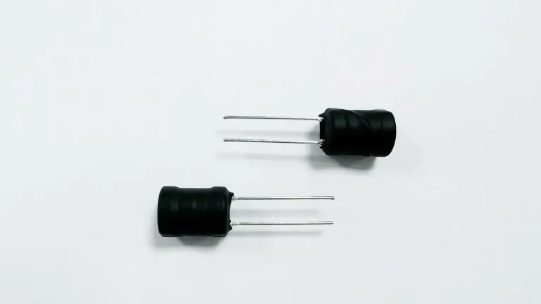
A custom rod core inductor uses an open magnetic path rather than a fully enclosed magnetic circuit. Instead of keeping most of the flux inside a closed core, the magnetic field extends through the surrounding air. The resulting higher magnetic reluctance can help reduce the risk of abrupt saturation during high-current operation.
This makes open magnetic path designs useful in power supplies, DC-DC converters, motor control circuits, and other applications where current peaks, thermal conditions, and available installation space must all be considered.
By adjusting the core dimensions, winding structure, wire size, and magnetic material, engineers can develop an inductor that better matches the electrical and mechanical requirements of a specific application.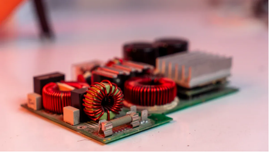
Open Magnetic Path Physics in Inductor Cores
An inductor converts electrical energy into magnetic energy when current passes through its winding. The core material provides a path for magnetic flux and strongly influences inductance, saturation behavior, and energy storage.
Ferrite offers much higher permeability than air, allowing magnetic flux to concentrate within the core. However, when the magnetic circuit includes a substantial air path, the total reluctance increases. This changes the way the component responds as current rises.
Feature | Closed Magnetic Path | Open Magnetic Path |
Flux Circuit | Mostly contained within the core | Extends through the air path |
Magnetic Reluctance | Low | Higher |
Saturation Behavior | Can become relatively sharp | Generally more gradual |
Main Energy Region | Magnetic core | Core and surrounding air |
Reluctance and Soft Saturation
A closed magnetic structure, such as a toroidal core, provides a low-reluctance path for magnetic flux. This is useful when high inductance density is required, but the core can approach saturation relatively quickly as current increases.
An open magnetic path introduces additional reluctance into the magnetic circuit. Since air has much lower permeability than ferrite, the air portion limits the overall flux density that develops inside the magnetic material.
As a result, inductance generally decreases more gradually with increasing current. This behavior is commonly described as soft saturation.
For power circuits exposed to short-duration current peaks, a gradual reduction in inductance can be preferable to an abrupt change. It gives the circuit a more predictable response during overloads and switching transients.
Energy Storage Under DC Bias
Energy storage is another important consideration when selecting an inductor for power conversion.
A magnetic component must maintain sufficient inductance while carrying its expected DC current. If the core enters deep saturation, inductance can fall significantly, affecting ripple current and overall converter behavior.
With an open magnetic path, a larger portion of the magnetic energy can be associated with the surrounding air region. Because air does not saturate in the same way as a ferromagnetic material, the structure can provide useful tolerance to DC bias.
This characteristic makes open-core configurations worth considering for high-current power supplies, motor controllers, filtering circuits, and other applications where the operating current varies substantially.
The trade-off is that an open structure allows more magnetic flux to extend outside the component. Therefore, electrical performance and electromagnetic compatibility must be evaluated together during circuit design.
Custom Rod Core Inductor Design
The main advantage of a custom rod core design is flexibility.
Rather than selecting a standard component and adapting the circuit around it, engineers can adjust the physical structure of the inductor according to the actual requirements of the application.
Core length, diameter, material, winding area, wire size, and turn count all influence the final electrical characteristics.
A longer or larger-diameter core can provide additional winding space and change the effective magnetic path. A smaller structure may help reduce the footprint but can place greater limits on current handling and thermal dissipation.
The right combination depends on the target inductance, operating current, switching frequency, temperature range, and available installation space.
Aspect Ratio and Winding Optimization
The ratio between core length and diameter affects the magnetic field distribution around the component. Engineers can use this relationship to balance inductance, saturation characteristics, and physical dimensions.
Winding design is equally important.
For high-current applications, thicker copper wire can reduce DC resistance and associated conduction losses. Flat wire may also be considered when a larger conductor cross-section is required within a limited winding area.
Turn spacing affects both electrical isolation and high-frequency behavior. Excessively tight winding can increase parasitic effects, while excessive spacing may increase the overall component size.
A custom winding structure therefore needs to balance several factors rather than simply maximizing the number of turns.
For switching applications, engineers may also evaluate AC resistance, skin effect, proximity losses, and temperature rise. These factors become increasingly important as operating frequency increases.
Thermal Management and EMI Considerations
Thermal performance is often one of the reasons engineers consider an open-core structure.
A rod core inductor exposes a relatively large portion of its surface to the surrounding air. With sufficient airflow, heat generated by the winding and core can be transferred to the environment without relying entirely on the PCB.
Lower operating temperature helps maintain more stable electrical characteristics during long operating cycles.
However, the open magnetic path also creates an important design consideration: stray magnetic flux.
Unlike shielded inductors, an open-core component allows part of its magnetic field to extend into the surrounding area. If the inductor is positioned too close to sensitive signal traces, sensors, communication lines, or feedback circuits, unwanted magnetic coupling may occur.
PCB layout therefore becomes part of the inductor design process.
Engineers may reduce interference by:
· Keeping sensitive signal traces away from the magnetic field region
· Positioning the component at an appropriate orientation
· Minimizing high-current loop areas
· Providing sufficient physical clearance
· Using localized shielding where necessary
· Separating power and control sections of the PCB
The goal is not necessarily to eliminate all external magnetic flux, but to control its interaction with nearby circuitry.
Power Electronics Applications for Open Path Inductors
Open magnetic path inductors can be used in several applications where current stability and soft-saturation characteristics are more important than maximum magnetic shielding.
High Current Filtering
Power supplies generate ripple currents during switching operation. An inductor placed in the filtering stage limits rapid current changes and helps smooth the output waveform.
At high load currents, maintaining usable inductance is critical. An open magnetic path can provide a gradual inductance response as current increases, making the component suitable for circuits with changing load conditions.
Engineers may use customized rod structures when a standard component cannot provide the required combination of inductance, current capacity, and mechanical dimensions.
DC-DC Conversion
Buck and boost converters depend heavily on their inductors.
During each switching cycle, the inductor stores and releases energy while controlling current ripple. If the component saturates too quickly, ripple current can increase sharply and place additional stress on switching devices and capacitors.
A properly designed rod core structure can provide predictable current behavior across the converter's operating range.
Core size, winding resistance, switching frequency, and saturation characteristics should be evaluated together rather than treating inductance as the only selection criterion.
Automotive and Industrial Power Circuits
Automotive and industrial electronics frequently experience rapid load changes. Motors, actuators, pumps, and switching converters can all generate short-duration current peaks.
A customized open-core inductor can be designed around these operating conditions.
For automotive applications, temperature cycling, vibration, installation space, and long-term reliability also need to be considered. Industrial equipment may place greater emphasis on continuous current, cooling conditions, and mechanical robustness.
The component therefore needs to match the complete operating environment rather than only the nominal electrical specification.
How to Select a Custom Rod Core Inductor
Selecting a custom component should begin with the actual circuit conditions.
Important parameters include:
Parameter | Why It Matters |
Inductance | Determines current ripple and filtering behavior |
Rated Current | Defines the expected continuous operating range |
Saturation Current | Indicates when inductance begins to decline significantly |
DC Resistance | Influences conduction loss and temperature rise |
Operating Frequency | Affects core and copper losses |
Core Material | Determines permeability and frequency characteristics |
Dimensions | Must fit the available mechanical space |
Temperature Range | Defines reliable operation under environmental changes |
EMI Requirements | Determines acceptable external magnetic field levels |
Current and Saturation Margin
Rated current alone does not provide enough information for high-current applications.
Engineers should examine the inductance-versus-current curve and identify how much inductance remains at the maximum expected load.
For circuits with large transient currents, additional margin is often necessary. A component that performs well at nominal current may behave very differently during startup, short-duration overloads, or sudden load changes.
The objective is to keep the inductor within a predictable operating region instead of designing directly at the saturation boundary.
Frequency and Loss Evaluation
Inductance values measured at low frequency may not fully represent component behavior in a switching converter.
At higher frequencies, core loss, winding resistance, skin effect, and proximity effect can increase. These losses contribute to temperature rise and reduce overall system efficiency.
For this reason, engineers should evaluate the component at the actual switching frequency whenever possible.
A custom winding can then be developed to reduce unnecessary copper loss while maintaining the required inductance and current capacity.
Why Customization Matters in Modern Power Designs
Standard inductors work well when their electrical and mechanical specifications already match the application. However, specialized power systems often impose several requirements at the same time.
A component may need to provide:
· High current capacity
· Controlled saturation behavior
· Low DC resistance
· Specific inductance
· Compact dimensions
· Improved heat dissipation
· A defined winding configuration
· Stable operation across temperature changes
Meeting all these requirements with an off-the-shelf component can be difficult.
A custom rod core inductor allows engineers to adjust the magnetic and winding structure around the actual circuit rather than compromising the circuit design to accommodate a fixed component.
This approach can be particularly useful for industrial power supplies, DC-DC converters, motor control systems, automotive electronics, and specialized energy conversion equipment.
The final design should always be validated through electrical testing, thermal testing, and, where relevant, electromagnetic compatibility evaluation.
Conclusion
Open magnetic path inductors provide a different balance between inductance, saturation behavior, thermal performance, and magnetic shielding compared with closed-core designs.
The additional air path increases magnetic reluctance and can produce a softer inductance response as current rises. This makes rod core structures useful in applications where current changes rapidly or where predictable behavior under DC bias is important.
At the same time, the open structure requires careful PCB placement and EMI consideration because part of the magnetic field extends beyond the core.
For demanding applications, customization provides greater control over core dimensions, winding geometry, wire selection, inductance, resistance, and thermal behavior. A properly engineered custom rod core inductor can therefore become a practical solution when standard inductors cannot meet the electrical and mechanical requirements of a specialized power system.
FAQ
What is the main benefit of an open magnetic path inductor?
The open magnetic path increases magnetic reluctance and can produce a more gradual reduction in inductance as current increases. This behavior is useful in high-current circuits with significant load variation.
Why choose a custom rod core inductor instead of a standard component?
Customization allows engineers to adjust the core size, winding structure, wire diameter, and inductance according to the actual circuit requirements. This is useful when standard component dimensions or electrical ratings are not suitable.
Are rod core inductors suitable for DC-DC converters?
Yes. Rod core structures can be used in DC-DC conversion circuits where current ripple, saturation behavior, thermal performance, and physical dimensions are carefully matched to the converter design.
Do open-core inductors create EMI problems?
They can produce more external magnetic flux than shielded structures. Proper component orientation, PCB spacing, current-loop control, and local shielding can help reduce unwanted magnetic coupling.
What should engineers check before selecting a rod core inductor?
Key factors include inductance, saturation current, DC resistance, operating frequency, core material, temperature range, physical dimensions, and the magnetic environment around the component.