 English
 Vietnamese
 Italian
 Spanish
 Thai
Thai Japanese
 Portuguese
 Korean
 Russian
 French
 German
 Polish
 Indonesian
The Application of I-Shaped Inductors in Smart Home Motor Drive Circuits
I-shaped inductors play a vital role in smart home motor drive circuits. They filter noise, stabilize current, and boost overall efficiency. These small components help designers meet the compact, quiet, and energy-saving demands of modern smart home devices.
Engineers value these inductors for their ability to smooth voltage fluctuations and suppress electrical interference. A well-chosen inductor also extends the life of motor drive circuits and keeps performance consistent across different operating conditions.
This article explains what an I-shaped inductor is, why it matters in motor drives, and which benefits it brings to smart home applications. Readers will also find practical guidance on selecting and integrating inductors into their own designs.
Key Takeaways
· I-shaped inductors filter noise and stabilize current in motor drives. These actions improve efficiency and extend circuit life.
· The compact design and high saturation current make these inductors perfect for small, powerful smart home devices.
· Choose the right inductor by matching inductance, current rating, and frequency to your driver. This selection ensures reliable performance.
· Place the inductor close to the driver and avoid sensitive sensors. Good placement reduces interference and keeps the system clean.
What Is an I-Shaped Inductor?
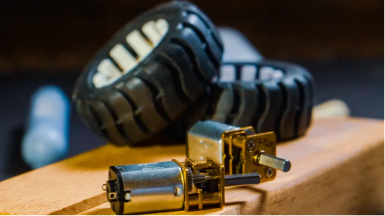
Structure and Core Principles
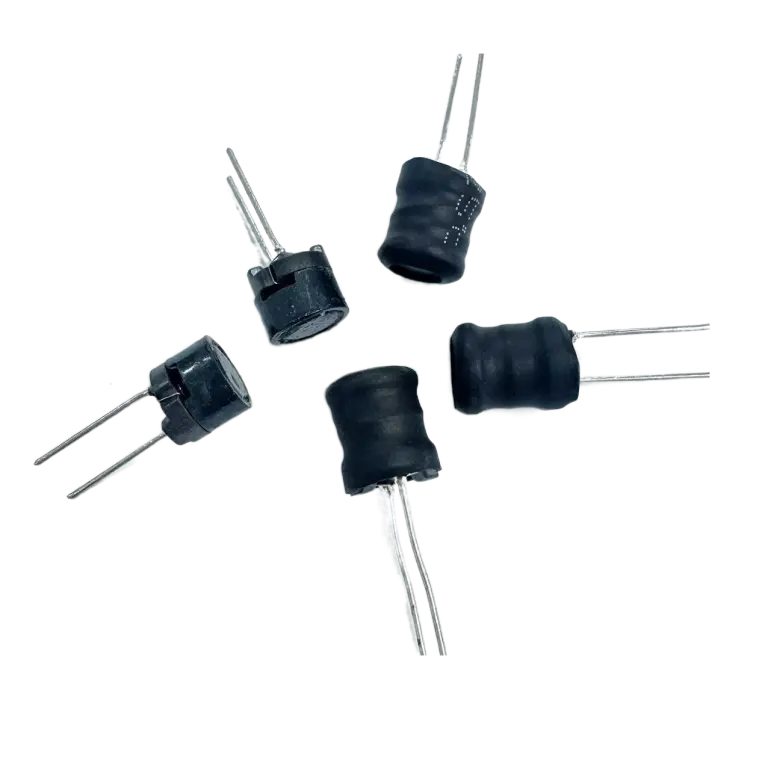
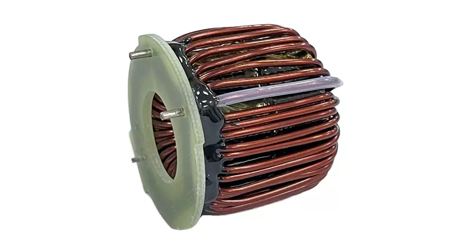
An I-shaped inductor uses a rod or bar-shaped magnetic core with wire windings wrapped around it. This design differs from toroidal or closed-loop types. The open structure gives engineers easy access for winding and assembly.
An inductor stores energy in a magnetic field when current flows through its coils. This property makes the component useful for smoothing voltage fluctuations and filtering high-frequency noise. The magnetic core concentrates the field lines and boosts inductance.
Ferrite cores support high-frequency operation with low energy loss. Designers widely use these cores in switching power supplies and filters. The material handles rapid switching without excessive heating.
Key Electrical Properties
The inductance of an inductor depends on core material, winding turns, and physical dimensions. A higher turn count raises inductance but also increases DC resistance. Engineers balance these trade-offs for each application.
The voltage and current of inductors follow a defined relationship. Voltage across the component depends on how fast the current changes over time. This behavior allows an inductor to oppose sudden shifts in current flow.
Ferrite materials perform well across a broad frequency range. They keep core losses low during AC operation. This trait suits power conversion circuits that switch at high speeds.
An I-shaped inductor also handles substantial current before saturation. The rod core design provides stable performance in compact spaces. These parts fit well in smart home motor drives and similar circuits.
Why Inductors Matter in Motor Drives
Drive circuits depend on inductors for filtering, oscillation, delay, and notching. An inductor shifts the phase of current relative to voltage. This phase relationship helps the drive start correctly and develop defined rotation direction and torque. Without this phase shift, the drive would produce inconsistent motion. Switching FETs and inductors together determine the size and performance of any power converter. Designers consider these components as the most influential parts in the converter layout. Modern switching circuits routinely achieve energy efficiency above 95 percent with carefully selected inductors.
Noise and EMI Suppression
Switching noise threatens the reliable operation of smart home devices. Inductors serve as motor drive filters that block high-frequency noise from spreading through the power supply. An inductor presents high impedance to high-frequency signals. This impedance increases as frequency rises. The inductor reflects noise back toward its source instead of letting it pass through. These parts are valuable filters for unwanted interference. The inductor attenuates sharp switching edges and reduces electromagnetic radiation from the system. This choking and filtering action keeps the power line clean for other sensitive components.
Effective EMI reduction requires matching the component to the switching frequency of the driver. A mismatch reduces filtering effectiveness and allows noise to escape. Designers combine inductors with capacitors to create line filters that remove both differential and common-mode noise. The inductor handles the series impedance while capacitors provide a shunt path to ground. These filter networks help the product achieve EMC/EMI compliance with regulatory standards. Passing these tests is essential for selling smart home products in global markets.
Current Smoothing and Thermal Control
An inductor resists sudden changes in current. This property makes it ideal for smoothing pulsed current from a switching converter. The inductor stores energy in its magnetic field when the switch is on. It releases that energy when the switch turns off. This action fills the gaps between pulses and creates a steady current flow through the windings. A smoother current reduces torque ripple and improves motion quality.
Smooth current also reduces ripple and prevents excessive heating in the system. Large current transients generate heat in the windings and in the drive electronics. The inductor limits the rate of change in the flow. This limitation reduces peak values and spreads the thermal load across the switching cycle. Lower operating temperatures extend the life of capacitors, FETs, and the drive itself. Thermal management becomes simpler when the inductor handles transient energy.
An inductor shapes the current and voltage waveforms inside the circuit. Proper waveform shaping reduces stress on the switching FETs and improves overall efficiency. A clean waveform contains fewer harmonics that would otherwise waste energy as heat. The inductor also helps maintain continuous current flow during light load conditions.
Frequency plays a direct role in component behavior and selection. Higher switching frequencies allow the use of smaller inductance values. Smaller inductors save board space and reduce component cost. The core material must support the operating frequency without excessive losses. Ferrite materials excel at high frequencies and keep core losses low. Designers must verify that the core does not saturate at peak current.
The AC current in the drive also affects performance. The alternating signal creates a changing magnetic field in the core. Core losses increase with frequency and with AC amplitude. These losses appear as heat that must be managed through proper design. Designers choose materials that balance core losses against the required inductance value for the application.
The I-shaped inductor is a common choice for these drive designs. Its open rod structure provides stable inductance in a compact footprint. The component handles high saturation levels before the core saturates. This margin ensures reliable operation during startup and fault conditions. The simple construction also keeps costs low for high-volume production.
Benefits for Smart Home Applications
Compact Size and High Saturation
Smart home devices demand small components that handle heavy loads. An I-shaped inductor delivers both qualities. Its rod core design packs high inductance into a tiny footprint. This compact size saves valuable board space in motor drive circuits.
High saturation current is another critical advantage. The inductor maintains stable performance when current spikes during motor startup. It does not lose inductance under peak load conditions. This reliability keeps the drive working through demanding operating cycles.
Gujing brings over 23 years of manufacturing expertise to this field. The company develops more than 20,000 magnetic core material formulations. Its production lines exceed 90 percent automation. These capabilities ensure consistent quality across every batch. Gujing holds IATF 16949 and ISO 9001 certifications.
Low Core Loss and Cost-Effectiveness
Low core loss translates directly into energy savings. The inductor wastes less power as heat during switching operations. This efficiency supports the quiet, cool operation that smart home users expect. Lower losses also reduce stress on nearby components.
Cost-effectiveness matters for high-volume consumer products. The simple construction of an I-shaped inductor keeps manufacturing expenses low. Gujing offers an extensive product range to match different design needs. The lineup includes the DLCH, DLCR, DLCP112, DLGB3X0912, DLGB3X0608, and DLGB3X series. Additional options cover the DLGBX1415, DLGBX1216, DLGBX1016, DLGBX0912, DLGBX0810, DLGBX0612, DLGBX0406, and DLGBX series.
These inductors serve switching power supplies, DC-DC converters, smart home devices, electric motors, LED drivers, and household appliances. The AC frequency response remains stable across operating conditions. Designers gain a flexible, affordable solution for voltage regulation and noise filtering.
Selecting the Right Inductor
Inductance and Current Ratings
The inductance value is the first specification a designer should determine. This value sets how much energy the component stores and how well it smooths current ripple. A higher inductance provides better filtering but responds more slowly to load changes. A lower inductance reacts faster but allows more ripple to pass through. Engineers calculate the target value from the switching frequency, the acceptable ripple level, and the load requirements of the motor drive.
The rated current defines the maximum load the part can handle continuously. Designers must also check the saturation current, which is the point where the core loses its magnetic properties. Exceeding this limit causes a sharp drop in inductance and can damage the drive. A safe design keeps the peak operating current well below the saturation threshold. Thermal derating matters too, because resistance rises with temperature and reduces the effective current capacity.
The voltage and current of inductors follow a defined relationship in every switching cycle. Voltage across the winding depends on how quickly the current changes over time. This behavior allows the component to oppose sudden shifts in flow. Designers use this principle to predict ripple and verify that the part meets the needs of the circuit.
Gujing offers customization services for unique inductance values, package dimensions, current ratings, or application-specific designs. Experienced engineers support every project from application evaluation and magnetic material selection to structural optimization, prototype production, performance verification, and mass manufacturing. This support helps designers move from concept to production without delays.
Frequency and Size Constraints
The operating frequency of the drive shapes the selection process. Higher switching speeds allow smaller inductance values, which saves board space and reduces cost. The core material must support the chosen frequency without excessive loss. Ferrite cores perform well across a broad frequency range and keep core losses low during AC operation. Designers verify that the core does not saturate at peak current under the worst-case load.
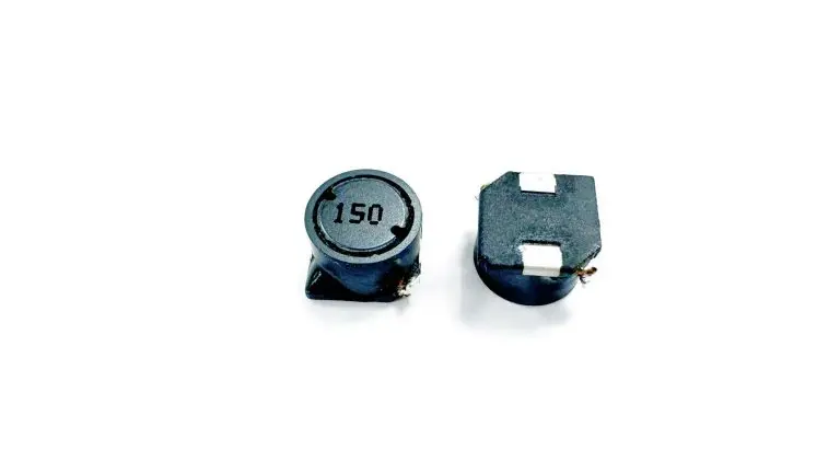
Size constraints often decide the final choice. Smart home devices pack many components into tight spaces, so every millimeter counts. An I-shaped inductor with a rod core delivers high inductance in a compact footprint. This design fits well in motor drive circuits where board area is limited. The open structure also simplifies automated assembly and keeps production costs low.
Designers should evaluate the DC resistance of the winding as well. Lower resistance means less power wasted as heat and better overall efficiency. The power handling capability of the inductor must match the drive requirements. A part with insufficient power capacity will overheat and fail prematurely.
Gujing provides technical support for component selection, application analysis, prototype development, and mass production. The company's product range includes the DLCH, DLCR, DLCP112, DLGB3X0912, DLGB3X0608, and DLGB3X series, along with the DLGBX1415, DLGBX1216, DLGBX1016, DLGBX0912, DLGBX0810, DLGBX0612, DLGBX0406, and DLGBX series. These inductors deliver stable inductance, low DC resistance, and reliable current handling. Designers can request samples and test them under real operating conditions before committing to a final specification.
Integration Tips for Motor Drivers
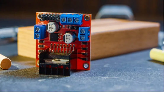
Placement and Shielding
Place the I-shaped inductor close to the motor driver output. Short traces between the inductor and driver reduce radiated interference. Proper current flow requires careful trace routing. The open rod structure creates a field that extends beyond the body. Orient the core axis away from sensitive signal paths. The pcb layout should include a ground plane beneath the inductor. Gujing precision winding technology ensures consistent parasitic values across batches.
The magnetic field from inductors can interfere with nearby sensors. Properly placed inductors reduce noise coupling into traces. Keep components away from antennas and hall-effect sensors. A grounded copper pour provides additional shielding. The dc resistance of the winding affects placement. Lower resistance generates less heat. Gujing uses optimized magnetic core materials that keep core losses low. This reduces the heat that the inductor radiates. Strict quality inspection and complete traceability ensure each part meets specifications.
Driver Compatibility
Match the inductor to the motor driver IC. The rated inductance must align with the driver switching frequency and output filters. A mismatch produces excessive ripple. The saturation current must exceed the peak driver output. The current rating of the component must match the driver requirement. The winding resistance affects power loss and overall power efficiency. Gujing automated manufacturing maintains tight tolerances on inductance values. Traceability ensures every batch matches the datasheet.
The driver operating frequency constrains the core material. Ferrite cores from Gujing support the frequency range in motor drive circuits. The core must not saturate during peak current transients. Saturation drops inductance and triggers fault conditions. Gujing quality inspection verifies core performance under extreme conditions. Automated production reduces variation. Engineers count on consistent behavior across units for inductors and other components. The component footprint must match the layout. Gujing inductors come in multiple series for different mounting requirements. The stable voltage output depends on proper inductor selection. Higher voltage applications require cores with higher saturation thresholds. Power delivery remains consistent.
I-shaped inductors deliver clear benefits in smart home motor drive circuits. They suppress noise, smooth current flow, and raise power efficiency. These parts help designers build compact, reliable, and affordable smart home devices. The inductor stores energy and releases it to stabilize voltage during switching. A well-chosen inductor also limits heat and extends circuit life. Engineers should apply the selection and integration guidelines from this article. Matching inductance, current rating, and frequency to the driver ensures stable performance. Proper placement and shielding reduce interference. These steps help any designer optimize motor drive circuits for modern smart home products.
FAQ
What does an I-shaped inductor actually do in a motor drive circuit?
It stores energy in a magnetic field and releases it to smooth current. The part also blocks high-frequency noise from reaching other components. This filtering action keeps the power line clean. The result is steadier motor motion and less electrical interference.
How does a designer pick the right inductance value?
The switching frequency and acceptable ripple level set the target. A higher value filters better but reacts slower to load changes. A lower value responds faster and passes more ripple. Engineers balance these trade-offs for each drive design.
Can Gujing supply custom inductors for a specific design?
Yes. Gujing offers customization for unique inductance values, package dimensions, current ratings, and application-specific designs. Engineers support projects from material selection through prototype production and mass manufacturing. The company holds IATF 16949 and ISO 9001 certifications.
Which product series fit smart home motor drives?
The DLCH, DLCR, DLCP112, DLGB3X0912, DLGB3X0608, and DLGB3X series cover many needs. The DLGBX1415, DLGBX1216, DLGBX1016, DLGBX0912, DLGBX0810, DLGBX0612, DLGBX0406, and DLGBX series address further size and performance requirements. These parts serve switching power supplies, DC-DC converters, electric motors, and household appliances.
Why does saturation current matter more than rated current?
Rated current defines continuous operation. Saturation current marks the point where the core loses inductance. Exceeding it causes a sharp drop in performance and possible damage. A safe design keeps peak current well below that threshold.