Complete Guide to Common Mode Inductors for EMI Noise Suppression
As electronic systems continue to become smaller, faster, and more integrated, electromagnetic interference (EMI) has become one of the most common challenges faced by hardware engineers. Whether designing industrial automation equipment, switching power supplies, electric vehicle charging systems, communication devices, or renewable energy converters, engineers must ensure that unwanted electrical noise does not affect system performance or prevent products from meeting EMC compliance requirements.
Among the many passive components used for noise control, the Common Mode Inductor plays an essential role. By suppressing common mode noise without significantly affecting differential signals, it helps improve signal integrity, enhances system reliability, and simplifies compliance with international EMC standards.
Unlike many articles that focus only on the basic definition of a common mode inductor, this guide takes a practical engineering perspective. We will discuss how common mode inductors work, where they should be used, how different structures compare, and what factors engineers should evaluate before selecting a component. Throughout the article, related technologies such as Common Mode Choke, EMI Common Mode Choke, EMC Common Mode Choke, Power Inductor, SMD Inductor, Through Hole Inductor, and other magnetic solutions will also be introduced where appropriate.
Whether you are developing a new product or optimizing an existing design, understanding the characteristics of common mode inductors can significantly improve electromagnetic compatibility while reducing design risks during product development.
What Is a Common Mode Inductor?
A Common Mode Inductor, often referred to as a Common Mode Choke, is a magnetic component designed to suppress common mode electromagnetic interference while allowing the desired differential current to pass with minimal impedance.
Unlike conventional inductors that mainly store energy, a common mode inductor is intended to filter unwanted noise generated by switching circuits, power converters, communication interfaces, or external electromagnetic sources.
The operating principle is relatively straightforward. Two windings are wound around a shared magnetic core. During normal operation, the differential currents flowing through the windings generate magnetic fields in opposite directions, causing them to cancel each other. As a result, the differential signal experiences very little impedance.
However, when common mode noise appears on both conductors with the same current direction, the magnetic fields reinforce one another, producing a much higher inductance. This increased impedance effectively blocks high-frequency noise from propagating through the circuit.
Because of this unique behavior, Common Mode Inductors have become standard components in:
AC power input filters
DC power systems
Switching power supplies
EV charging equipment
Industrial control systems
Communication infrastructure
Medical electronics
Renewable energy converters
Consumer electronic devices
Unlike an ordinary Power Inductor, which primarily stores energy inside DC-DC converters, a common mode inductor is specifically optimized for electromagnetic noise suppression.
Why EMI Has Become a Bigger Challenge Than Ever
Electronic equipment today operates at significantly higher switching frequencies than products designed only a decade ago. Higher efficiency often comes at the cost of increased electromagnetic emissions.
Several factors contribute to this trend.
First, switching frequencies in modern power supplies continue to rise. Gallium Nitride (GaN) and Silicon Carbide (SiC) devices enable converters to operate at hundreds of kilohertz or even several megahertz. Faster switching edges generate wider EMI spectra that can easily couple into surrounding circuits.
Second, equipment has become more compact. Components are placed closer together, increasing parasitic capacitance and inductive coupling. Noise that once remained localized can now propagate throughout an entire system.
Third, more electronic products must coexist within shared environments. Industrial factories, hospitals, telecommunications facilities, electric vehicles, and smart homes all contain numerous electronic systems operating simultaneously. Effective noise control is therefore no longer optional.
Finally, global EMC regulations continue to evolve. Manufacturers seeking international market access must ensure their products satisfy increasingly stringent conducted and radiated emission requirements.
These developments explain why EMI Common Mode Chokes and EMC Common Mode Chokes have become standard components in modern circuit design rather than optional additions.
How Does a Common Mode Inductor Work?
Understanding the operating mechanism helps engineers make better design decisions instead of selecting components solely based on inductance values.
A typical Common Mode Choke consists of two identical windings sharing one magnetic core.
Under normal operating conditions:
Current enters one winding.
The return current flows through the second winding.
Their magnetic flux cancels almost completely.
The useful power signal passes through with minimal loss.
When common mode interference appears:
Noise flows in the same direction through both windings.
Magnetic flux adds together.
Inductance increases dramatically.
High-frequency interference encounters high impedance.
Noise energy is greatly reduced before reaching sensitive circuits.
This operating principle allows one component to distinguish between useful electrical signals and unwanted interference without requiring complex active circuitry.
The effectiveness of a Common Mode Inductor depends on multiple design factors, including:
Core material
Winding symmetry
Leakage inductance
Core permeability
Operating frequency
Saturation characteristics
Temperature stability
These characteristics explain why products designed for industrial automation may differ significantly from Automotive Inductor solutions or communication-grade magnetic components.
Main Types of Common Mode Inductors
Not every common mode inductor is suitable for every application. Different structures are optimized for different operating environments, installation methods, and current ratings.
Through Hole Common Mode Inductors
The traditional Through Hole Common Mode Choke remains widely used in industrial equipment because of its excellent mechanical strength and high current capability.
Compared with surface-mounted devices, through-hole components generally offer:
Better vibration resistance
Larger magnetic cores
Higher current capacity
Longer service life in harsh environments
Easier heat dissipation
They are frequently found in:
Industrial power supplies
UPS systems
Servo drives
Variable frequency drives
Heavy-duty automation equipment
Many manufacturers also combine these designs with Through Hole Inductor technologies for complete power filter solutions.
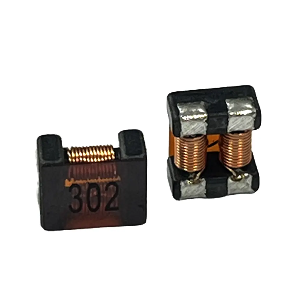
SMD Common Mode Inductors
As electronics continue to shrink, SMD Common Mode Choke products have become increasingly important.
Surface mounting provides several practical advantages:
Automated PCB assembly
Reduced assembly cost
Compact footprint
Improved production consistency
High-speed manufacturing compatibility
Modern SMD Inductor manufacturing techniques also allow excellent dimensional consistency while maintaining stable electrical performance.
Typical applications include:
Consumer electronics
Smart home devices
Communication modules
IoT products
Portable medical equipment
Although physically smaller than through-hole versions, many modern SMD Common Mode Chokes provide excellent suppression across a broad frequency range.
Toroidal Common Mode Chokes
The Toroidal Common Mode Choke is widely recognized for its outstanding magnetic efficiency.
Its closed magnetic path minimizes leakage flux while maximizing magnetic coupling between the windings.
Key advantages include:
Excellent EMI suppression
Low magnetic leakage
High efficiency
Stable inductance
Reduced acoustic noise
Because of these characteristics, toroidal structures are frequently selected for:
Industrial converters
Renewable energy equipment
Solar inverters
High-power battery systems
Motor drives
Engineers often combine Toroidal Inductor solutions with common mode filters when designing complete EMI suppression systems.
Ferrite Common Mode Chokes
Ferrite remains one of the most commonly used magnetic materials in electromagnetic interference filters.
A Ferrite Common Mode Choke provides:
High permeability
Excellent high-frequency characteristics
Low core losses
Stable electrical performance
Good cost-performance balance
Ferrite materials are especially effective in suppressing conducted noise generated by high-speed switching circuits.
Nanocrystalline Common Mode Chokes
For applications requiring exceptionally high permeability and superior low-frequency suppression, Nanocrystalline Common Mode Chokes are becoming increasingly popular.
Compared with conventional ferrite materials, nanocrystalline cores generally provide:
Higher initial permeability
Better low-frequency attenuation
Higher saturation flux density
Lower core losses
Improved temperature stability
These characteristics make them particularly suitable for:
Renewable energy systems
Large industrial converters
High-current power electronics
Grid-connected equipment
Although not necessary for every application, nanocrystalline technology has become an important option in demanding EMI environments.
Common Mode Inductor vs Differential Mode Choke
One of the most common misunderstandings among new engineers is assuming that a Common Mode Choke and a Differential Mode Choke perform the same function.
Although both components contribute to EMI reduction, they target completely different types of interference.
A common mode inductor suppresses noise that appears simultaneously on both conductors relative to ground. This type of interference often originates from parasitic capacitance inside switching devices or high-speed power converters.
A differential mode choke, on the other hand, suppresses noise flowing in opposite directions between two conductors. Differential noise is usually generated by switching current ripple and converter operation.
In practical filter design, engineers frequently combine both components. A complete input EMI filter may include:
Common Mode Choke
Differential Mode Choke
X capacitors
Y capacitors
Additional Power Choke solutions
Optimized PCB grounding
Rather than competing technologies, these components complement each other to achieve comprehensive EMI suppression.
Key Parameters Engineers Should Evaluate Before Selection
Selecting a Common Mode Inductor should never be based on inductance value alone. A component that performs well in one application may fail to meet the requirements of another if critical operating conditions are overlooked.
One of the first parameters to consider is the rated current. The inductor must withstand the maximum continuous operating current without driving the magnetic core into saturation. Once saturation occurs, the impedance drops sharply and the component loses much of its noise suppression capability. For applications involving motor drives, power converters, or industrial equipment, choosing a High Current Common Mode Choke with adequate current margin is often the safer approach.
The operating frequency range is equally important. Different magnetic materials exhibit different impedance characteristics across the frequency spectrum. Ferrite cores typically perform well at high frequencies, while nanocrystalline materials offer stronger attenuation at lower frequencies. Matching the core material to the dominant noise frequency can significantly improve filter effectiveness.
Mechanical considerations should also not be overlooked. PCB space, mounting method, thermal conditions, and vibration requirements all influence the final component choice. Compact consumer electronics may favor SMD Common Mode Chokes, whereas industrial control systems often rely on larger through-hole designs for enhanced mechanical stability and current handling.
Finally, engineers should evaluate long-term reliability rather than focusing solely on initial electrical specifications. Core material consistency, winding precision, insulation quality, and manufacturing control all contribute to stable performance throughout the product's service life. Selecting a reliable Inductor Manufacturer with proven experience in magnetic component production can reduce variability between production batches and improve overall product reliability.
Applications of Common Mode Inductors Across Different Industries
One of the main reasons the Common Mode Inductor has become a standard component in modern electronic systems is its versatility. While the basic operating principle remains the same, the design priorities often vary depending on the application environment, electrical characteristics, and regulatory requirements.
Rather than selecting a common mode inductor solely by inductance value, experienced engineers evaluate how the component will perform under real operating conditions. Current level, switching frequency, ambient temperature, installation space, and EMC standards all influence the final design.
The following industries illustrate why different common mode inductor structures continue to evolve alongside advances in power electronics.
Switching Power Supplies
Switching power supplies are among the largest sources of conducted EMI because power MOSFETs and wide-bandgap semiconductor devices switch at extremely high speeds. Fast voltage transitions generate common mode currents that travel through parasitic capacitance into the AC input line.
Installing a properly selected EMI Common Mode Choke at the power input helps reduce these unwanted currents before they propagate through the electrical system.
Engineers typically combine the choke with X capacitors, Y capacitors and other filtering components to form a complete line filter. In compact power supplies, a Power Inductor may also be used alongside the common mode choke to improve converter stability while reducing differential ripple.
Applications include:
AC-DC power supplies
Industrial switching power supplies
Adapter power supplies
LED driver power supplies
Telecom power systems
Industrial Automation Equipment
Modern factories rely heavily on high-frequency switching equipment such as PLC controllers, servo drives, robotic systems and motor inverters. These systems often operate continuously under demanding electrical environments where conducted and radiated noise can interfere with nearby equipment.
A carefully selected High Current Common Mode Choke improves system stability by reducing conducted interference on both power and signal lines.
Industrial equipment also tends to require components capable of operating over a wide temperature range while maintaining stable inductance under continuous load. This is one reason why many manufacturers continue to choose Through Hole Inductor solutions and larger magnetic cores for industrial applications.
Common applications include:
Variable frequency drives (VFDs)
Servo motor controllers
PLC control cabinets
Industrial robots
Machine vision systems
Factory automation equipment
Electric Vehicles and Automotive Electronics
Automotive electronics have become significantly more complex over the past decade. Electric vehicles now integrate numerous high-power converters, battery management systems, onboard chargers, DC-DC converters and motor control units within a relatively compact space.
Each switching converter becomes a potential source of EMI.
To ensure stable operation, designers frequently incorporate Automotive Inductor, Automotive Power Inductor, and Automotive Common Mode Choke solutions throughout the vehicle.
Compared with industrial electronics, automotive components face additional challenges:
Wide operating temperature ranges
Continuous vibration
High humidity
Long service life
Strict EMC regulations
High reliability requirements
Many automotive projects therefore specify magnetic components that comply with AEC-Q200 qualification requirements. Stable magnetic materials, precise winding symmetry and reliable insulation become equally important as electrical performance.
Typical automotive applications include:
Onboard chargers
Battery management systems
DC-DC converters
EV charging modules
Electric steering systems
Automotive communication networks
Renewable Energy Systems
Solar inverters, battery storage systems and wind energy converters operate under high voltage and high current conditions while switching continuously throughout the day.
These applications generate significant conducted noise because of large switching currents and complex converter topologies.
For renewable energy equipment, engineers often choose Toroidal Common Mode Choke, Energy Storage Inductor, and High Current Power Inductor solutions that combine excellent magnetic efficiency with low core losses.
Typical renewable energy equipment includes:
Solar inverters
Photovoltaic converters
Battery energy storage systems
PCS equipment
Wind power converters
Charging infrastructure
As renewable energy systems continue increasing in power density, the demand for higher-performance magnetic components is expected to grow steadily.
Medical Electronics
Medical devices require not only reliable electrical performance but also exceptionally low electromagnetic emissions.
Diagnostic equipment, patient monitoring systems and laboratory instruments often operate alongside highly sensitive electronic circuits. Even relatively small amounts of conducted noise may influence measurement accuracy.
For this reason, compact SMD Common Mode Choke solutions are frequently used inside medical equipment where PCB space is limited while EMC performance remains critical.
Communication Equipment
Modern communication hardware continues moving toward higher transmission speeds.
Servers, optical communication equipment, industrial Ethernet devices and wireless infrastructure all rely on clean power delivery to maintain signal integrity.
A properly designed Ferrite Common Mode Choke helps suppress conducted interference before it reaches sensitive communication circuits, reducing packet loss and improving overall system stability.
How to Choose the Right Common Mode Inductor
Although many products may share similar inductance values, they can perform very differently in actual applications. Selecting the right component requires balancing electrical performance, mechanical design and long-term reliability.
The first consideration should always be the application itself rather than the catalog specification.
Evaluate the Noise Source
Before selecting any magnetic component, engineers should identify where the interference originates.
Questions worth considering include:
Is the dominant noise common mode or differential mode?
Which switching device generates the interference?
What is the switching frequency?
Which regulatory standard must be satisfied?
Understanding the noise source allows the filter to be designed more efficiently instead of relying on oversized components.
Select an Appropriate Core Material
Core material largely determines impedance characteristics across different frequency ranges.
Ferrite materials remain suitable for many commercial products because they provide stable high-frequency performance.
Nanocrystalline cores are increasingly selected where stronger low-frequency attenuation or higher permeability is required.
For very high current applications, material saturation characteristics become particularly important.
Confirm Rated Current
Choosing an undersized component can lead to magnetic saturation during normal operation.
Once saturation occurs:
Inductance decreases sharply.
Noise suppression performance deteriorates.
Temperature rise increases.
EMC performance becomes inconsistent.
Selecting a High Current Common Mode Choke with sufficient operating margin helps maintain stable performance throughout the product lifecycle.
Consider Installation Method
Mechanical structure directly affects manufacturing efficiency.
For automated PCB production, SMD Inductor solutions generally offer faster assembly and smaller footprints.
Industrial equipment requiring higher current capacity or stronger mechanical reliability often continues to use Through Hole Inductor designs.
The installation method should therefore match both electrical requirements and manufacturing processes.
Evaluate Thermal Performance
Temperature influences magnetic permeability, winding resistance and insulation reliability.
Applications operating inside enclosed cabinets or high-power converters should include adequate thermal margin when selecting magnetic components.
Designers should avoid selecting components based solely on room-temperature specifications.
PCB Layout Considerations for Better EMI Performance
Even the highest quality Common Mode Choke cannot compensate for poor PCB layout.
EMI performance depends on both component selection and circuit implementation.
Several design principles consistently improve filter effectiveness.
First, place the common mode choke as close as possible to the power entry point. Preventing noise from spreading across the PCB is usually more effective than attempting to suppress it later.
Second, minimize loop area. Larger current loops increase magnetic radiation and reduce filter performance.
Third, maintain symmetry between differential conductors. Unequal trace lengths may increase leakage inductance and reduce common mode attenuation.
Fourth, separate noisy switching circuits from sensitive analog or communication circuits whenever possible.
Finally, ensure grounding strategies are planned during the early stages of PCB design rather than after EMC testing reveals problems.
In practice, successful EMC performance is rarely achieved through one component alone. It results from the combined optimization of magnetic components, PCB layout, grounding, shielding and enclosure design.
Common Mistakes Engineers Should Avoid
Many EMC issues are caused not by component defects but by inappropriate selection or system-level design decisions.
One common mistake is choosing a component solely according to inductance value. While inductance is important, parameters such as rated current, saturation characteristics, impedance curve and operating frequency are equally significant.
Another frequent error involves ignoring temperature rise. Components tested under laboratory conditions may experience substantially higher temperatures inside enclosed industrial equipment.
Some designers also underestimate the influence of PCB routing. A well-designed EMC Common Mode Choke may provide limited improvement if noisy traces bypass the filter entirely.
It is also common to overlook manufacturing consistency. Differences in core material quality, winding accuracy and insulation processes can lead to noticeable variations between production batches. Working with an experienced Inductor Manufacturer capable of maintaining consistent manufacturing standards helps reduce these risks during mass production.
Finally, engineers sometimes apply identical filter designs across different products without evaluating each application's specific EMI characteristics. Although similar circuits may appear interchangeable, differences in switching frequency, cable length or enclosure construction can significantly affect overall EMC performance.
Why Manufacturing Quality Matters in Common Mode Inductor Performance
The electrical characteristics shown in a datasheet represent only one aspect of a Common Mode Inductor. In practical applications, long-term reliability depends just as much on manufacturing quality as on the initial design.
Two components may have identical nominal inductance values, yet perform differently after months or years of operation because of variations in materials, winding precision, insulation systems, or production consistency. For engineers developing industrial equipment, automotive electronics, or renewable energy systems, these differences can directly influence EMC performance, product reliability, and maintenance costs.
Several manufacturing factors deserve particular attention during supplier evaluation.
Core Material Consistency
The magnetic core determines how effectively a common mode inductor suppresses high-frequency interference. Variations in permeability, saturation characteristics, or core density can alter impedance across the operating frequency range.
Reliable manufacturers maintain strict control over raw material selection and incoming inspection to ensure consistent magnetic properties between production batches. This is particularly important for Ferrite Common Mode Choke and nanocrystalline designs used in demanding EMI environments.
For equipment expected to operate continuously over many years, consistent core quality helps maintain stable common mode inductance throughout the product lifecycle.
Winding Accuracy and Magnetic Balance
The effectiveness of a Common Mode Choke depends on the symmetry of its windings.
Even small differences between the two coils may increase leakage inductance, reduce common mode attenuation, or introduce unnecessary differential mode effects. Precision winding equipment and well-controlled manufacturing processes help ensure balanced electrical performance.
For high-frequency applications, maintaining accurate winding geometry becomes even more important because parasitic capacitance and leakage flux have a greater influence on EMI suppression.
Insulation Reliability
Many electronic systems operate under elevated voltages, high humidity, or frequent thermal cycling.
Reliable insulation between windings protects both electrical safety and long-term stability. High-quality insulation materials also reduce the risk of degradation caused by vibration, moisture, or repeated temperature changes.
This consideration is especially important for applications such as:
Industrial automation
EV charging equipment
Renewable energy converters
Medical power supplies
Communication infrastructure
Process Control During Production
Stable production processes are essential for maintaining consistent electrical performance.
Professional manufacturers typically implement quality control throughout multiple production stages, including:
Raw material inspection
Automated winding verification
Core assembly inspection
Electrical parameter testing
Hi-pot and insulation testing
Visual inspection
Final sampling before shipment
These procedures reduce variation between production lots and help ensure that every component performs as expected once integrated into customer equipment.
When Should You Consider a Custom Common Mode Inductor?
Standard catalog products satisfy the needs of many applications. However, certain projects require electrical or mechanical characteristics that are difficult to achieve with off-the-shelf components.
A Custom Common Mode Choke may provide better performance when engineers face challenges such as:
Limited PCB space
Higher current requirements
Unique mounting structures
Special impedance curves
Wide operating temperature ranges
Industry-specific EMC standards
Custom development also allows optimization of core materials, winding structures, insulation systems, and package dimensions according to the requirements of the final application.
For example, an EV charging module may prioritize high current capability and thermal performance, while a communication device may focus on minimizing parasitic capacitance and improving high-frequency attenuation. Although both products require common mode filtering, their design priorities differ considerably.
Working with an experienced Custom Inductor supplier early in the development process often shortens the design cycle by reducing repeated EMC testing and PCB redesign.
Common Mode Inductors and Other Magnetic Components
A common mode inductor rarely works in isolation. Modern electronic systems usually employ multiple magnetic components, each serving a different function within the power or signal path.
A complete design may include:
Power Inductor for energy storage
Integrated Inductor for compact DC-DC converters
Shielded Inductor for reduced magnetic radiation
Through Hole Inductor for high-current industrial applications
SMD Inductor for compact PCB layouts
Power Choke for differential filtering
Transformer assemblies for voltage conversion
Selecting the appropriate combination of components enables engineers to balance efficiency, thermal performance, EMC compliance, and available installation space.
As electronic systems continue to increase in power density, cooperation between different magnetic components becomes increasingly important.
Future Trends in Common Mode Inductor Technology
The next generation of electronic equipment places higher expectations on passive magnetic components than ever before.
Several industry trends are driving continuous innovation in Common Mode Inductor design.
Higher Switching Frequencies
The adoption of GaN and SiC semiconductor technologies allows converters to operate at much higher frequencies than conventional silicon devices.
While this improves efficiency and reduces system size, it also increases electromagnetic interference. Future High Frequency Common Mode Choke designs will require improved core materials capable of maintaining stable impedance across broader frequency ranges.
Higher Power Density
Power supplies, automotive electronics, and renewable energy equipment continue to deliver more power within smaller enclosures.
To support these developments, magnetic components are becoming more compact while maintaining high current capability. Improved thermal design and optimized winding techniques will remain key areas of development.
Electrification and Renewable Energy
Electric vehicles, photovoltaic systems, battery storage installations, and charging infrastructure continue expanding worldwide.
These applications require reliable Automotive Common Mode Choke, Vehicle Grade Common Mode Inductor, and high-current magnetic components capable of operating under demanding environmental conditions.
As power conversion systems become more sophisticated, demand for advanced EMI suppression solutions will continue to grow.
Increased Automation in Manufacturing
Modern magnetic component production increasingly relies on automated winding equipment, precision inspection systems, and digital quality management.
Higher manufacturing consistency benefits customers by improving electrical stability, reducing product variation, and supporting large-scale production requirements.
Selecting the Right Manufacturing Partner
Component selection extends beyond choosing a suitable part number. Long-term project success also depends on the capabilities of the manufacturing partner.
When evaluating an Inductor Manufacturer, engineers and purchasing teams often consider factors such as:
Product development experience
Manufacturing consistency
Quality management systems
Engineering support
Customization capability
Production capacity
Technical documentation
Long-term supply stability
Projects involving industrial automation, automotive electronics, communication equipment, and renewable energy frequently require ongoing technical collaboration rather than simply purchasing standard components.
For this reason, companies often prefer working with suppliers capable of providing both standard products and customized magnetic solutions.
Manufacturers offering a broad portfolio—including Gujing Common Mode Inductor, Gujing Power Inductor, Gujing SMD Inductor, Gujing Through-hole Inductor, Gujing Integrated Inductor, and other Gujing Magnetic Component solutions—can better support different stages of product development while simplifying supplier management for OEM and ODM projects.
Conclusion
As electronic products become more powerful, compact, and interconnected, controlling electromagnetic interference has become an essential part of circuit design rather than a final-stage consideration. A properly selected Common Mode Inductor helps suppress conducted noise, improves electromagnetic compatibility, protects sensitive circuits, and contributes to long-term system reliability.
Choosing the right solution involves more than comparing inductance values. Engineers should evaluate current rating, operating frequency, magnetic material, thermal characteristics, installation method, and manufacturing quality together to ensure the component matches the application's actual operating conditions.
Whether the project involves industrial automation, power conversion, communication equipment, renewable energy systems, or automotive electronics, selecting dependable magnetic components and working with an experienced Gujing Inductor Manufacturer can simplify development while improving product consistency.
For applications requiring standard products or customized magnetic solutions, portfolios covering Gujing Common Mode Inductor, Gujing Power Inductor, Gujing SMD Inductor, Gujing Automotive Inductor, Gujing Custom Inductor, and other Gujing Inductors provide engineers with flexible options for addressing evolving EMC challenges across a wide range of industries.