English
 Vietnamese
 Italian
 Spanish
 Thai
 Japanese
 Portuguese
 Korean
 Russian
 French
 German
 Polish
 Indonesian
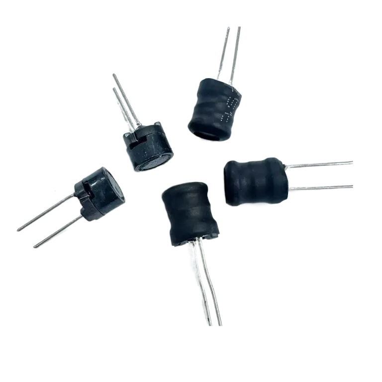
5 Ways Rod Inductor Manufacturers Ensure Consistent Inductance
Consistent inductance in mass production rests on five manufacturing disciplines: core material selection, automated winding with tension control, in-line inductance testing with feedback, thermal and environmental control, and statistical process control with audits. Small inductance variation shrinks tuning margins, shifts circuit performance, and lowers production yield. Engineers and procurement teams evaluating a rod inductor manufacturer face one practical question: which techniques and controls actually hold inductance within tolerance across large runs? The five disciplines below answer that question directly, showing what each control contributes and what to verify during a supplier audit.
Precise Core Material Selection
Specifying Magnetic Properties
Inductance rises in direct proportion to magnetic permeability. An air-core coil produces a weak magnetic field. Inserting magnetic material into that coil concentrates the field and significantly boosts both inductance and the Q-factor. This physical relationship makes core specification the first lever for consistency. A rod inductor manufacturer that controls permeability at the source controls inductance downstream.
The choice of inductor core material sets the baseline for every unit that follows. Engineers specify a grade with a defined permeability range, then verify that grade against the application's frequency and current demands. Precision manufacturing processes then hold inductance accuracy within plus or minus twenty percent. That window depends on stable effective permeability across the production run. A shift in the supplied core material moves every winding on the line at once.
Lot-Level Testing Before Winding
Lot-level characterization catches permeability drift before any wire goes onto a core. Each incoming lot of inductor core material passes a sample test for permeability and dimensional consistency. Suppliers compare results against the characterized distribution for that grade. A lot that falls outside the range never reaches the winding station.
This gate protects the tolerance window run after run. The same discipline applies to toroidal inductors and coils, where core grade governs the achievable inductance band. Documented lot data also supports traceability during a supplier audit. Buyers can request these records and confirm that core material control is a measured process, not an assumption. Consistent core material, verified lot by lot, keeps the ±20 percent window achievable across large runs.
Automated Winding with Tension Control
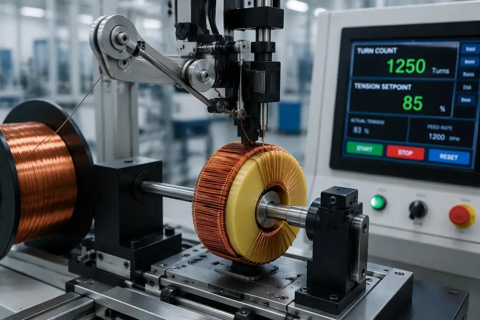
Turn Count and Winding Density
The winding process is the core step in inductor manufacturing. It sets inductance value, inductance stability, and overall performance. Precision winding technique keeps coil dimensions consistent in high-volume manufacturing. Automated equipment counts winding turns and lays them in even layers. Each copper wire turns count must match the design, because every added turn strengthens the magnetic field. A single misplaced turn changes that field, so the machine places every turn at the same pitch.
Uniform turn density minimizes inductance variation across units. Excessive overlapping of turns in single-layer windings should be avoided to keep inductance consistent. A disciplined winding process also fixes the number of winding turns per layer. Wire diameter and layer spacing shape the final value, and the machine holds both within the programmed recipe. This discipline overlaps with toroidal inductor process controls, where turn distribution and tension management serve the same consistency goals. The same logic applies to toroidal inductors and coils, and to toroidal inductors & coils built on toroidal cores.
Closed-Loop Tension Systems
Wire tension governs how tightly wire windings sit on the core. Loose wire windings shift position and alter the magnetic circuit. Closed-loop tension systems measure tension continuously and adjust it in real time. Mechanical dancers, servo-driven feeders, and load cells each hold the wire at a set pull. The controller compares each reading against the setpoint and corrects the motor. Controlled tension keeps every unit close to its target inductance.
These controls also support the toroidal inductor process, and they serve toroidal inductors and coils in the same way. Stable tension preserves the geometry of the wire windings through handling and potting. Tension control completes the winding process. Documented tension logs give auditors a record of the setpoint and the measured range for each run. The result is repeatable performance across the full production run.
In-Line Inductance Testing and Feedback
Catching Drift at the Winding Station
In-line measurement catches inductance drift before parts leave the winding station. A dedicated test head reads each finished coil as it exits the machine. Operators see the result immediately, while the part is still in hand. This early inductance check stops a drifting run from building a full batch of out-of-tolerance units.
Test fixturing must account for coil position on the rod. Sliding the coil along a ferrite rod changes inductance, the same principle used to tune AM radio antennas. A fixture that seats the part at a fixed reference point removes that variable. The measurement then reflects the coil itself, not where the operator happened to place it. Stable fixturing keeps the reading tied to the target inductance level for every unit.
Closing the Feedback Loop
Measurements feed back into winding parameters, so corrections happen within the run rather than after it. When readings trend high or low, the controller adjusts turn count or tension on subsequent parts. The line returns to its target inductance without stopping production or scrapping the batch.
The same feedback discipline applies to testing toroidal inductors and coils, where winding geometry also governs final inductance. Turn distribution on toroidal cores shifts the final inductance value, so the loop corrects geometry the same way it corrects rod windings. Documented measurement records give auditors proof that the loop closes on every run.
Thermal Compensation and Environmental Control
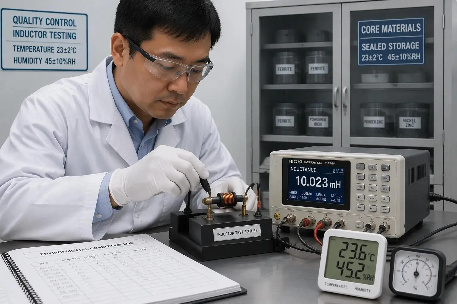
Managing Temperature Effects
Temperature shifts magnetic permeability, and inductance follows that shift. A core material that performs well at room temperature can drift once the winding heats during operation. Manufacturers address this by selecting core material grades with stable permeability across the rated temperature band. They also choose inductors rated for high thermal endurance. That rating supports consistent inductance values, minimal magnetic loss, and long-term operational stability.
Thermal compensation extends to the production floor. Winding and test stations run at controlled temperatures, so measurements reflect the part rather than the room. A test reading taken in a cold morning bay and another taken in a warm afternoon bay can differ for reasons unrelated to the coil. Holding the station temperature steady removes that variable. The same logic applies to toroidal inductors and coils, where core temperature affects the final inductance reading just as it does on a rod.
Controlling Humidity and Handling
Humidity and handling conditions during manufacturing also affect wound cores. Moisture uptake can alter the effective properties of the core material, and rough handling can shift turn positions on a finished coil. Both effects move inductance away from its target. Environmental controls at the winding and test stations protect the tolerance window against these influences.
Practical controls include humidity monitoring, sealed storage for sensitive core material, and defined handling procedures at each station. Operators use fixtures rather than bare hands to move finished coils. These steps keep the magnetic permeability of each core stable from incoming inspection through final test. The discipline carries over to toroidal inductors and coils, where handling and moisture control protect the same consistency goals. Documented environmental logs give auditors a clear record of station conditions during each production run.
Statistical Process Control and Audits
SPC Charts for Early Detection
Statistical process control charts track inductance measurements across a manufacturing run. Each plotted point represents a tested unit, and the chart shows the trend as the run progresses. A slow upward drift appears as a rising line long before any single part fails. Operators catch that drift early and correct it before it becomes scrap. This early warning protects the tolerance window and reduces waste in large-scale manufacturing.
Control limits come from characterized process capability, not from guesswork. The manufacturer studies a stable run, measures the natural spread of inductance values, and sets limits around that spread. Points inside the limits show a process in control. Points outside the limits trigger an investigation. A rod inductor manufacturer that builds limits from real capability data gives auditors a defensible basis for every decision on the line.
Lot Sampling and Final Audits
Lot sampling and final inductance audits form the last verification layer. A sample drawn from each lot undergoes measurement against the characterized distribution. The audit confirms that shipped units match the distribution the process was built to produce. This step does not rely on a single end-of-line check. It verifies the whole lot against the statistical record.
The same audit discipline applies to toroidal inductors and coils, where winding geometry governs final inductance. Auditors compare sample results with the distribution for toroidal cores and flag any lot that falls outside it. Documented audit records complete the inductor quality assurance chain. Buyers can review these records and confirm that every shipped lot matches its target inductance and the characterized distribution.
Five controls carry inductance consistency from design to shipment. Core material selection sets the magnetic baseline, automated winding with tension control fixes coil geometry, in-line testing with feedback corrects drift within the run, thermal and environmental control protects the tolerance window, and statistical process control with audits verifies every lot. No single step delivers performance consistency alone. A capable rod inductor manufacturer layers all five, so each one catches what the others miss. Engineers and procurement specialists should ask suppliers for lot-level core data, tension logs, in-line measurement records, station environmental logs, and SPC charts built from characterized capability. A rod inductor manufacturer that shares these records demonstrates control over inductance across large runs.