English
 Vietnamese
 Italian
 Spanish
 Thai
 Japanese
 Portuguese
 Korean
 Russian
 French
 German
 Polish
 Indonesian
How Does a Common Mode Inductor Manufacturer Keep EMI Strong?
A common mode inductor manufacturer keeps electromagnetic interference suppression strong through three core controls: precise winding tension, automated winding machinery, and rigorous lot testing. Balanced, repeatable windings preserve the impedance curve, and that curve delivers the noise suppression. Tension errors or uneven turns shift parasitic capacitance and leakage inductance, so the part no longer matches its design target. Automated lines hold each coil to the same geometry, and lot testing confirms the result before shipment. Together, these controls turn a good prototype into a reliable production part.
Why Winding Consistency Drives EMI Filtering
How a Common Mode Choke Separates Noise
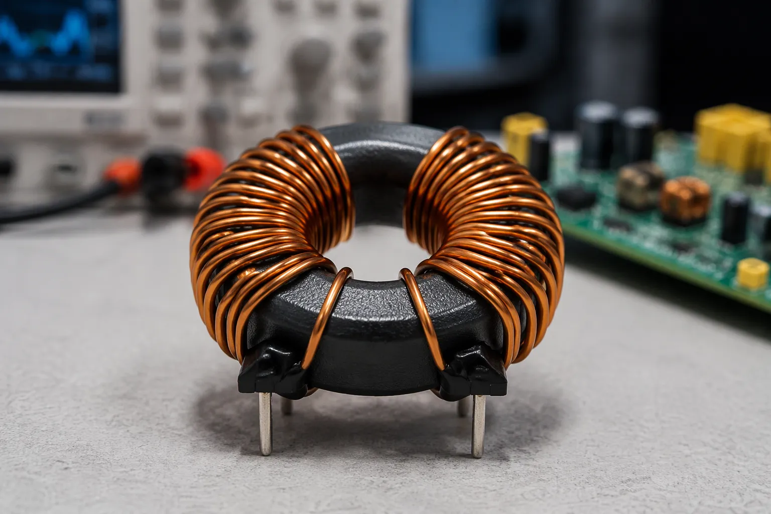
A common mode choke works as a frequency-selective gate. It presents low impedance to differential-mode working signals and high impedance to common-mode noise currents. Signal current flows in opposite directions through the two coils, so the magnetic fields cancel and the part looks nearly transparent. Noise current flows in the same direction on both lines, so the fields add and the part blocks the path. This selective behavior is the heart of emi filtering.
Balanced, coupled windings on a single core make that separation possible. Tight magnetic coupling between the two coils keeps the differential path clean and the common-mode path resistive. A well-made common-mode choke therefore passes power and data while filtering out common mode noise. The common-mode impedance curve defines how well the part performs across frequency, and the winding arrangement sets that curve.
How Winding Variation Weakens EMI Filtering
Small process shifts move the impedance curve away from its design target. Turn spacing changes the parasitic capacitance between layers. Wire tension changes how tightly the coils sit against the core. Winding position changes leakage flux. Each of these shifts alters winding inductance and winding resistance, and the frequency response drifts with them.
Uneven coils blur the distinction between the two noise paths. Coupling weakens, differential signal sees more impedance, and common mode noise sees less. The part still functions, yet its emi suppression falls short of the design intent. Common-mode inductance drops at the high end of the band, exactly where many designs need the most attenuation.
Unit-to-unit variation turns this into a production problem. One lot may pass an EMC compliance run while the next fails on the same test setup. Engineers then face rework, retesting, and schedule slips. Field performance becomes unpredictable, because common mode currents that a good part would block now travel further into the system. Consistent windings protect the frequency response, and a stable frequency response protects electromagnetic interference performance across every unit shipped.
How a Common Mode Inductor Manufacturer Controls Winding
Automated Winding and Tension Control
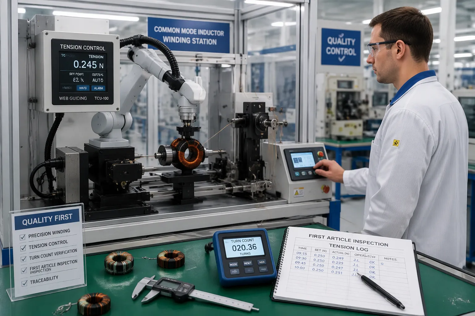
Automatic winding machines form and place flat copper wire with high precision. The machine controls the winding arrangement turn by turn, so each coil matches the same geometry as the last. Consistent coil geometry produces repeatable electrical performance, and repeatable performance keeps the impedance curve on target. A common mode inductor manufacturer invests in this equipment because manual winding cannot hold the same discipline across thousands of units.
Closed-loop tension control holds wire tension inside a tight window throughout the winding process. The system measures tension continuously and corrects the feed before the wire drifts loose or stretches too far. Loose windings reduce magnetic coupling between the coupled windings and raise winding resistance. Over-stretched wire stresses insulation and shifts the winding position against the core. Either error weakens emi filtering, so the tension window protects both reliability and noise suppression.
Skilled operators set up each run and monitor the line. They load the correct wire, confirm the program, and watch the first coils closely. The machine handles repetition; the people handle judgment. This division of labor keeps winding techniques stable from shift to shift and from lot to lot.
Batch Consistency and In-Process Checks
Verification happens at several points during production. At line start, first-article inspection confirms the turn count, the winding configuration, and the tension settings before the run continues. Operators then check turn counts at defined intervals and log tension readings against the approved window. These records create a traceable history for every batch.
Statistical process control monitors winding parameters over time. The team plots tension, turn count, and related readings, then watches for trends rather than waiting for failures. A slow drift triggers correction before it becomes a defect. This discipline protects yield and electromagnetic interference performance at the same time, and EMS providers weigh both when they choose a supplier.
Batch consistency also supports optimized winding configurations. When the process holds steady, engineers can tune the winding arrangement for a target frequency response and trust that production will reproduce it. Stable winding techniques reduce winding losses and keep winding and core losses predictable across the run. A common mode inductor manufacturer that reviews this data regularly catches problems early, and early correction costs far less than a failed lot.
Buyers should treat batch consistency as a sourcing question, not a technical footnote. A supplier with logged tension data and reviewed control charts demonstrates control over the common mode choke. That control is what separates a catalog promise from a shipped part.
Verifying EMI Performance in Common-Mode Chokes
Impedance and Insertion Loss Testing
Testing proves the design intent survives production. Engineers sweep impedance across frequency and compare each lot against the approved design curve. A matching curve confirms the part will suppress common mode noise as intended. Insertion loss measurement goes further, showing direct evidence of emi attenuation in a live circuit. Together, these two tests reveal whether a common-mode choke still performs after winding, assembly, and handling.
Compliance testing against CISPR and FCC limits anchors the result to recognized standards. High-current designs often target consistent emi attenuation around 20 kHz, where switching noise concentrates. A stable impedance response across the band matters more than a single peak value. When the frequency response holds flat and predictable, filtering out common mode noise becomes a design certainty rather than a hope.
What to Ask a Common Mode Inductor Manufacturer
Buyers should probe the process, not just the datasheet. Ask what tension tolerances the line holds and how often the team reviews SPC data. Ask whether the supplier shares lot-level test data with each shipment. These answers expose how tightly the common mode inductor manufacturer controls winding resistance and frequency response from batch to batch.
Request impedance curves and insertion loss reports for the specific part number. Generic catalog data says little about the actual common-mode chokes in the box. A supplier confident in its process will supply lot traces without hesitation. Those traces show how well the windings suppress common mode noise and how consistently common mode currents stay blocked. Strong emi suppression lives in the documents, not the marketing copy.
Strong EMI performance rests on four controls: a balanced winding arrangement, tension held inside a tight window, automated winding machinery, and lot-level verification. Each control protects the impedance curve, and the curve delivers the noise suppression.
Winding consistency is a process discipline, not a single inspection step. A common mode inductor manufacturer earns trust through logged tension data, reviewed control charts, and shared lot traces. Readers comparing suppliers can carry the questions from this post as a practical checklist. Ask about tension tolerances, SPC review cadence, and part-specific impedance curves. The answers separate controlled production from catalog promises.