English
 Vietnamese
 Italian
 Spanish
 Thai
 Japanese
 Portuguese
 Korean
 Russian
 French
 German
 Polish
 Indonesian
How to Control Saturation Current and Heat in I Shaped Inductors
Engineers control saturation current and heat in I-shaped inductors through four levers: core material, core geometry and gap, winding design, and thermal or operating conditions. Measurement then confirms the design margin.
I-shaped cores have an open magnetic path. They saturate earlier than gapped or toroidal cores, so designers must build margin in from the start.
A practical decision order keeps the work focused. First choose the material, then the size, then the turns, then the wire, then the airflow, and finally verify the result. This sequence suits power inductors in any dc-dc converter or similar circuit. Each choice affects inductance and loss, so the steps belong together.
Saturation and Heat Fundamentals
Saturation Current vs. Rated Current
An inductor must always run below two separate limits. The rated current is the level at which the part meets its thermal limits. The saturation current marks the point where the core can no longer store the required energy. These are independent constraints. A part can overheat while still below saturation, or it can saturate while still below its thermal rating. Both checks are mandatory.
Parameter | What it defines | Failure mechanism it guards against |
Saturation current (Isat) | Current at which inductance falls by a specified percentage (e.g., 20–30%) | Excessive inductance loss / energy-storage collapse during current peaks |
RMS / rated current (Irms) | Current producing a defined temperature rise | Copper loss and overheating under specified conditions |
"when the inductor enters saturation, it can store less energy and the ripple current increases — meaning that the efficiency will be reduced."
There is no fixed universal percentage margin that the saturation current rating must exceed the expected peak current by. The right margin depends on current-limit behavior, startup and transient currents, component tolerances, temperature effects, and the shape of the dc superposition characteristic. Designers should size the margin against the worst credible current condition.
Sources of Heat in I-Shaped Inductors
Heat comes from two loss families. Core losses include static hysteresis, classical eddy current, and residual dynamic effects. Copper loss splits into a DC term from the dc current and an AC term from ripple, skin effect, proximity effect, and fringing fields around the gap. Termination and nearby conductors add contact resistance and induced currents.
Optimization should target total dissipation and hot-spot temperature rather than forcing core loss and winding (copper) loss to be equal; there is no universal requirement for the two to match.
This link matters because heat and magnetic saturation are not separate problems. A designer who watches how inductance changes in relation to dc current can predict the dc superposition rated current and the temperature increase rated current together. Keeping peak current below the saturation level protects energy storage. Keeping RMS current within the temperature increase rated current protects the winding. The dc superposition characteristic ties both behaviors to one curve, so one measurement informs both decisions.
How to Control Saturation Current
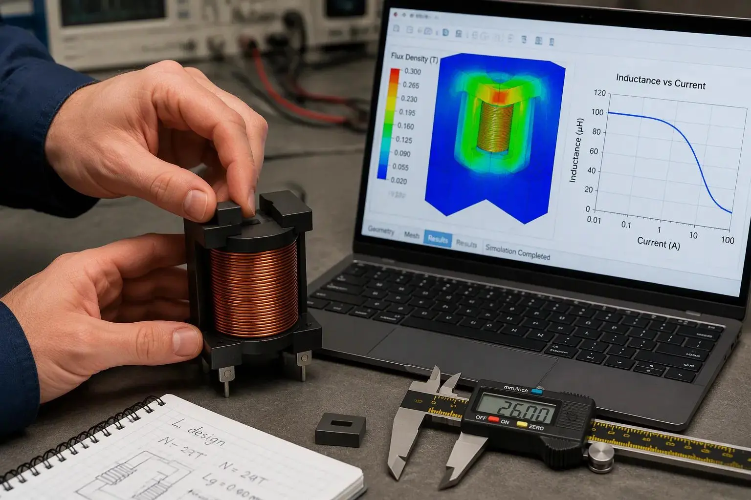
Engineers who understand magnetic flux can anticipate on-load behavior before a prototype exists. Flux density rises with applied volt-seconds and falls with core cross-section and turns. That relationship lets a designer predict where magnetic saturation begins, reduce core losses, and keep inductance stable across the load range. The same knowledge shows how to control saturation current without guesswork.
Core Material and Geometry for Power Inductors
Material choice sets the ceiling. A core's saturation flux density defines the flux level it can hold before permeability collapses. Ferrite, powdered iron, and alloy powder materials differ in that ceiling and in their loss behavior, so the selection should match the peak current the circuit demands.
Geometry sets how efficiently the core uses that ceiling. A larger effective cross-section spreads flux and supports higher current without saturation. A longer magnetic path raises the ampere-turns needed to reach the same flux level. I-shaped cores concentrate flux in a small volume, so geometry decisions carry more weight than they do in closed-core designs.
One trade-off deserves attention. Raising the saturation current rating amplifies the magnetic field around the part, and a stronger field can increase electromagnetic interference. The right answer is a balance: enough headroom for peak current, plus layout and shielding measures that keep emissions acceptable. Neither goal should cancel the other.
Turns, Gap, and Inductance
Turns and gap together control the inductance and current saturation parameters. More turns raise inductance but lower the current at which the core saturates. A gap in the magnetic path raises the saturation threshold and stabilizes inductance under dc current, at the cost of some inductance per turn.
Saturation current should be specified as the maximum current before core saturation occurs. Below that point, inductance stays consistent under load. Above it, inductance falls sharply and current rises faster than the designer intended. A clear specification prevents inductance from dropping during transient peaks in a dc-dc converter.
The dc superposition characteristic ties these choices together. This curve plots inductance against dc current, and its knee marks the practical saturation point. Reading the knee gives the dc superposition rated current directly. Designers who check this curve early can control saturation current in a dc-dc converter before winding and thermal work begins, and they can confirm the margin again in a second dc-dc converter variant without repeating the full analysis.
Heat Control in I-Shaped Inductors
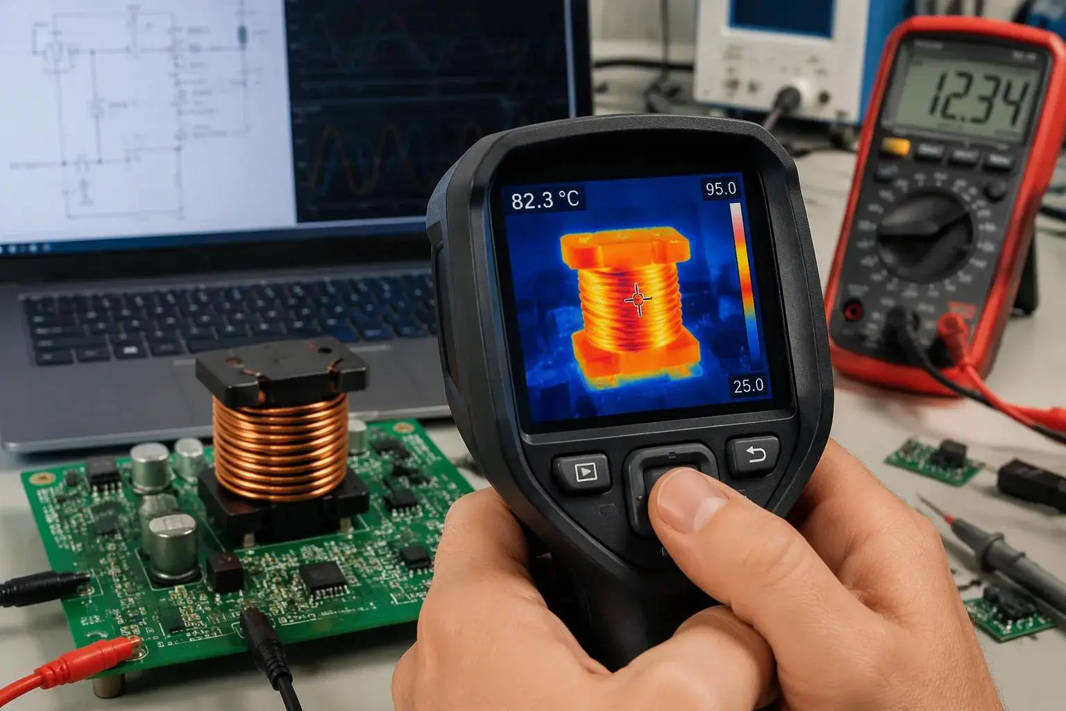
Heat control starts with the winding and ends with the environment around the part. Both halves deserve equal attention, because a well-made winding still runs hot inside a crowded enclosure with no airflow.
Conductor and Winding Design
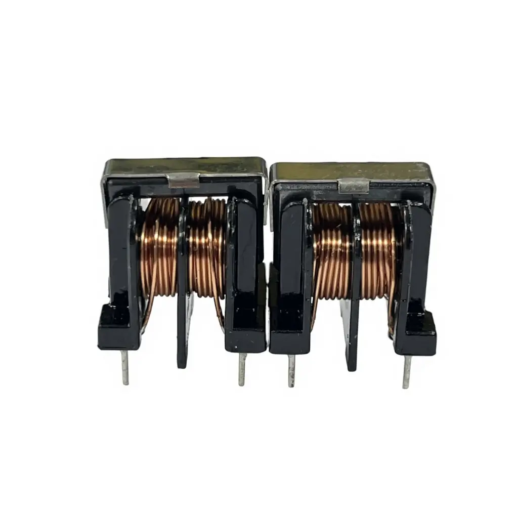
Wire gauge is the first lever on copper loss. A thicker wire lowers DC resistance and cuts the resistive heating that dominates at high dc current. The gain has a limit, since a thicker wire takes more window area and can push the winding into a larger package.
Winding layout decides where heat concentrates. A spread, single-layer winding exposes more surface to the air and avoids the stacked turns that trap heat in the middle of the coil. Multi-layer windings save space but raise localized heating, so designers should weigh compactness against heat dissipation.
Current ripple adds a second loss term. Ripple current flows through a frequency-dependent resistance, so the winding heats more than a pure dc current of the same average value would suggest. A part that stays cool under a dc test can still run hot in a switching circuit.
Operating mode matters too. In discontinuous conduction mode, the inductor current falls to zero every switching cycle. This raises RMS-current-related losses and creates abrupt current transitions that aggravate EMI. Delaying or preventing entry into DCM helps suppress the current-interruption effects that feed EMI. In a fixed-inductance PFC stage, the converter tends toward discontinuous operation near the low-current parts of the rectified mains waveform. A stepped-gap PFC inductor supplies higher inductance at low current and narrows that window, which reduces distortion and EMI.
Thermal Paths and Operating Conditions
A part rated for a given temperature rise in still air will behave differently on a real board. PCB copper area, nearby heat sources, airflow, switching frequency, ripple amplitude, core material, mounting layout, and ambient temperature all shift the actual temperature increase. Designers should treat the datasheet temperature increase rated current as a starting point and confirm it in the enclosure.
The thermal path runs from the winding through the core, the leads, and the PCB pads. Wide pads and generous copper planes spread heat and help the inductor handle higher current levels without overheating. Poor airflow removes that margin quickly.
Sourcing is one more variable. Gujing offers I-shaped inductor families such as DLCH, DLCR, DLCP112, DLGB3X, and DLGBX, plus customization for specific inductance, size, and current ratings. These parts appear in switching power supplies, dc-dc converter designs, consumer electronics, communication equipment, industrial control, LED drivers, appliances, motors, and smart home devices. Buyers should compare any family against their own thermal test data.
Measuring Saturation and Temperature
Saturation Tests and Margins
A pulse-circuit test reveals where magnetic saturation begins. The bench setup applies short current pulses to the inductor and captures the resulting waveform on an oscilloscope. The operator sets the supply to 0 V, connects the positive terminal to the drain side of the inductor, and ties the negative terminal to the bottom of the current shunt. A PWM source runs at 20 kHz with a 5% duty cycle and drives the MOSFET gate through a 47 Ω gate resistor. The scope triggers on the gate rising edge, with one channel on the gate and one across the shunt. The supply current limit should sit at 1.5× the expected saturation current.
The operator then raises the supply voltage slowly from 0 V toward the target, typically 5–15 V, while watching for a linear current ramp. Small duty-cycle steps of 1–2% follow. A true saturation signature is a knee-up: the ramp curves upward with a steeper slope. Ringing looks different, appearing as a sinusoidal ripple on the ramp. A flattening slope usually means supply current limiting or shunt self-heating, not saturation. Reducing the shunt resistance, using a four-wire Kelvin shunt, and keeping the ground lead short suppress ringing.
During a saturation event, a capacitor can initially absorb the voltage spike. A resistor then controls the charging and discharging current and dissipates the stored energy as heat. This network protects the test circuit while the operator records the knee.
Datasheet Checks and Load Testing
Datasheet review must cross-check two figures separately. The table below shows why a headline rating can mislead.
Parameter | Value |
Inductance | 1.5 µH |
Rated current | 1.4 A |
Saturation current | 1.1 A |
Calculated nominal peak current | 1.187 A |
The rated current exceeds the calculated peak, so the part looks acceptable at first glance. The saturation current sits below the peak, so the part fails the saturation screen. Designers should compare the inductance-drop threshold used for saturation current against the temperature-rise condition used for rated current, and confirm both curves use comparable conditions.
A load-and-temperature test closes the loop. The engineer runs the candidate on the target PCB under actual cooling conditions and records component temperature at steady state. This step confirms the thermal margin and the dc superposition characteristic in the real enclosure, not just on paper.
Four levers control saturation current and heat in an I-shaped inductor: core material, geometry and gap, winding design, and thermal or operating conditions. Measurement confirms the margin at every stage.
A prioritized action list keeps the work orderly:
1. Choose material and size for peak current, sizing the margin against the worst credible current condition.
2. Set turns and gap to fix inductance under load.
3. Select wire for low loss and manageable heat.
4. Verify with a load-and-temperature test.
Designers should treat saturation and heat as linked variables. A change that helps one shifts the other, so power inductors deserve joint review. The same discipline carries into any dc-dc converter layout.