English
 Vietnamese
 Italian
 Spanish
 Thai
 Japanese
 Portuguese
 Korean
 Russian
 French
 German
 Polish
 Indonesian
Key Electrical Parameters to Specify When Ordering OEM/ODM Inductors
A custom inductor order succeeds or fails on the specification sheet. Seven electrical parameters decide the outcome: inductance and tolerance, DCR, rated and saturation current, SRF, temperature coefficient and operating range, and core losses. Over-specification raises cost, size, and lead time. Under-specification invites saturation, overheating, resonance, and field failures. These parameters also interact. Lower DCR often means a larger body, and higher inductance lowers SRF. The goal is a balanced, application-driven spec. A structured selection process, from requirement definition through sample verification, helps engineers translate application needs into a clear specification for a gujing custom inductor.
Inductance Value and Tolerance
The nominal inductance value sets the circuit's operating point. The tolerance band defines how far production parts may drift from that point. Engineers should specify both on the RFQ, because a bare nominal value gives the manufacturer no acceptance window. Common inductor families hold a fairly consistent tolerance:
Inductor Type | Inductance Tolerance |
Bobbin-based inductors | ±10% (industry-standard primary inductance tolerance) |
Iron powder core inductors | ±10% (with high maximum flux density up to 15,000 gauss) |
Why Inductance Tolerance Matters
Inductance directly shapes ripple current in switching converters, cutoff frequency in filters, and energy storage per cycle. A part at the low edge of the band carries more ripple and may approach saturation sooner. A part at the high edge shifts a filter's corner frequency and can alter loop stability. Tolerance therefore acts as a performance guarantee, not a formality. The specification should state the nominal value, the tolerance band, and the test frequency and bias conditions under which the manufacturer measures both.
Setting a Realistic Tolerance Band
A ±10% band covers most bobbin-based and iron powder core designs and keeps cost and lead time reasonable. Tightening the band below that level usually demands extra sorting or tighter core grading, and the price rises accordingly. Three pitfalls deserve attention. First, over-tight tolerance adds cost without real circuit benefit. Second, inductance drifts over temperature, so the room-temperature band alone may not protect performance across the operating range. Third, a tolerance quoted at one test frequency may not hold at the application's switching frequency. The spec should name the measurement frequency and note any temperature drift allowance, so the approved sample and the mass-production part are judged on the same basis.
DC Resistance (DCR)
DC resistance sets the conduction loss of the winding. Engineers should treat it as an efficiency budget item, not a datasheet afterthought.
DCR and Power Loss
DC resistance converts current into heat through the winding. The DC copper loss equals the square of the DC winding current multiplied by the winding resistance at operating temperature. A 2 A current through a 50 mΩ winding dissipates 0.2 W as heat, for example. That heat raises the winding temperature, and the higher temperature raises DCR again. A room-temperature datasheet value therefore underestimates the real loss in a warm enclosure. DC copper loss is also only one part of the total. Skin and proximity effects add AC winding loss at higher frequencies, and core loss adds more. The sum of these three losses determines efficiency and the final operating temperature.
Setting a Practical DCR Limit
The specification should state a maximum DCR at a defined test temperature, and the buyer should confirm that temperature with the manufacturer. Package size drives the trade-off. A given inductance in a smaller package typically carries higher DCR and lower saturation current, because the windings are tighter and thinner. The table below shows the general trend.
Package | Relative DCR | Efficiency Impact |
0402 chip | High | Negligible at signal levels |
0805 chip | Moderate | Low |
CD43 power | Low | Moderate, watch at 2 A+ |
NR6045 | Very low | Minimal, suited for high current |
1770 series | Extremely low | High-current efficiency optimized |
A DCR limit without a reference temperature gives the manufacturer no verifiable acceptance criterion.
Battery-powered designs often make DCR the deciding factor between two otherwise equivalent packages. RF and resonant circuits instead prioritize Q factor. Buyers should also remember that DCR alone cannot explain high-frequency heating. The spec should pair the DCR limit with AC resistance data, ripple waveform, and operating frequency.
Rated vs. Saturation Current
Defining the Two Current Ratings
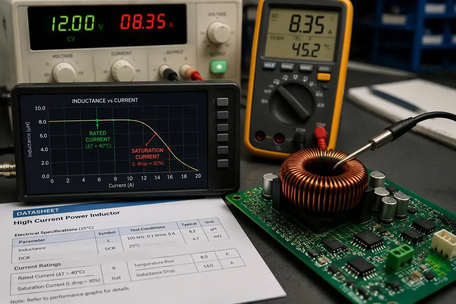
Rated current and saturation current describe two different limits, and engineers should never treat them as interchangeable. Rated current, also called thermal current, is the maximum current that produces a defined temperature rise above ambient. Saturation current is the peak current at which the core begins to lose inductance. The table below summarizes the standard definitions and the main points of manufacturer variation.
Parameter | Standard definition | Manufacturer variation |
Rated current (thermal current) | Maximum current for a defined temperature rise above ambient, commonly 20°C or 40°C | The temperature-rise threshold differs, so ratings are not directly comparable |
Saturation current | Peak current at which inductance has dropped by a defined percentage | The inductance-drop percentage varies: often 30% or 35%, some use 20%, others 40% |
Soft-saturation cores, such as distributed air-gap ferrite and powdered iron, roll off progressively instead of dropping sharply. Hard-saturation cores show a cliff-edge drop. A buyer who compares two datasheets without checking these definitions may select a part that saturates early or runs too hot.
Specifying Current for Gujing Custom Inductors
The specification should state which saturation definition applies, expressed as a percentage inductance drop, and confirm it with the manufacturer before release. Over-specifying current beyond the application's real need adds size and cost without benefit. A worked example shows why both ratings matter.
An inductor may be rated 6 A saturation and 4 A thermal. In a 4 A converter with 40% ripple, peak current (~4.8 A) stays below the 6 A saturation limit, yet the 4 A RMS current already meets the thermal rating exactly — before ambient temperature, nearby heat sources, or airflow are considered.
Gujing's selection support helps engineers match current levels to application requirements, and the team can confirm the saturation definition used for each gujing custom inductor. The RFQ should list the RMS current, the peak current, the ripple percentage, and the expected ambient temperature. These four values let the manufacturer verify both ratings against the real operating condition.
Self-Resonant Frequency (SRF)
SRF and Usable Frequency Range
Self-resonant frequency marks the point where an inductor's own parasitic capacitance cancels its inductance. Turn-to-turn capacitance, pad capacitance, and coupling to nearby conductors all contribute to that parasitic value. Together with the inductance, they form a parallel resonant circuit. Far below SRF, the coil behaves inductively and impedance rises with frequency. Near SRF, the part presents its highest impedance. Above SRF, the device turns capacitive and impedance falls as frequency climbs. A 100 nH inductor with 0.25 pF of parasitic capacitance reaches an SRF of about 1.01 GHz, for example. The part stays inductive below that point and capacitive above it.
This behavior sets a hard ceiling on usable frequency. Filtering, matching, and isolation all degrade once the part crosses into its capacitive region. Designers should therefore treat SRF as a design limit, not a datasheet curiosity.
Specifying SRF for Switching and Filtering
The specification should state a minimum SRF above the application's operating band. Common guidance calls for an SRF at least 2–3 times the highest operating frequency. RF circuits often demand a wider margin, with some design practices recommending at least 10 times the operating frequency. The RFQ should name the highest frequency the part will see, including switching harmonics and EMI filter stopbands, so the manufacturer can confirm the margin.
The most common pitfall is ignoring SRF in high-frequency switching or EMI filter designs. A part selected on inductance and current alone may sit close to resonance, where effective inductance and phase shift become highly frequency-sensitive. The filter then attenuates less than expected, or the converter loop behaves unpredictably. Buyers should also account for PCB parasitic capacitance at the operating frequency, because board layout shifts the effective SRF downward. Pairing the SRF limit with a Q factor requirement at the operating frequency gives the manufacturer a complete high-frequency target.
Temperature Coefficient and Range
Inductance vs. Temperature Behavior
Temperature coefficient describes how much inductance shifts as temperature changes. Core permeability drives most of that shift, and the effect is far from trivial. Ferrite cores in the industrial temperature range typically show inductance variation of ±10–30%. Some ferrite materials lose up to 50% of their permeability between 25°C and 100°C. A designer who approves a sample at room temperature may therefore receive a part that behaves very differently in a warm enclosure.
The specification should state the temperature coefficient or the allowable inductance drift across the operating range, together with the reference temperature. Buyers should also ask about Curie temperature, the point where the core loses its magnetic properties entirely. Permeability stability near that point degrades well before the core fails. Material choice matters here. Sendust (Fe-Si-Al) cores suit automotive and wide-temperature-range applications, and AEC-Q200 often specifies Sendust for this reason. Composite and molded parts deserve incoming inspection at elevated temperature; suppliers test Isat at 85°C and reject 5–8% of parts for falling below rated Isat at that temperature.
Matching Range to the Application
The operating temperature range must cover the real thermal environment, not just ambient air. Nearby heat sources, enclosure rise, and self-heating from copper and core losses all push the part above room temperature. The RFQ should state the minimum and maximum temperatures the inductor will see, including self-heating, and pair that range with the inductance drift allowance.
A wide range raises cost and narrows material options, so over-specifying wastes budget. Automotive and drone designs often need the full wide range, while a bench-top consumer product may not. The specification should list the range, the drift limit, and the test method in one place. That combination lets the manufacturer select a core material that holds inductance within the stated band across the whole range, and it gives the approved sample and the production part a shared acceptance basis.
Core Losses
Core Loss and Thermal Design
Core loss comes from two internal mechanisms: magnetic hysteresis and eddy currents. Material properties such as electrical resistivity and flux density set the magnitude, and operating conditions such as ambient temperature, output current, and switching frequency shift it. These losses leave the core as heat. That heat lowers efficiency and constrains the thermal design, and excessive heat can cap power density, force extra cooling, and shorten component life.
Efficiency peaks when core loss and copper loss balance. Engineers should not minimize either one alone. Core loss depends on ripple current and switching frequency from the application, plus core material, geometry, and air gaps from the design. The balance shifts with frequency. A traditional ferrite design at 100 kHz may swing 150–200 mT of AC flux, while a high-frequency ferrite design at 0.5–1 MHz swings only 20–50 mT. At high frequency, core loss, not saturation flux, sets the usable flux-density ceiling. The same material at the same flux swing loses roughly 150 times more power when frequency rises tenfold, from 100 kHz to 1 MHz.
Specifying Core Loss at Operating Conditions
A core-loss target only means something when tied to the application's real conditions. The RFQ should name the material grade, the actual flux swing, the switching frequency, the waveform and duty cycle, the operating temperature, and the core geometry. Material family alone cannot carry a loss figure; the specific grade must. The buyer should then check the selected core against the manufacturer's core-loss, permeability-versus-frequency, temperature, and DC-bias curves at those conditions.
Conventional frequency-domain measurement assumes near-sinusoidal waveforms, and that assumption fails for the sharp knees of real PWM excitation. Time-domain methods such as the one-pulse method avoid the sinusoidal assumption and match the test pulse to the converter's actual gate signals and bus voltages. The resulting inductance-current data feed behavioral models that predict core loss under realistic excitation. Total inductor loss equals DC copper loss plus AC winding loss plus core loss, so the specification should treat all three together rather than in isolation.
Application Priorities for Gujing Custom Inductors
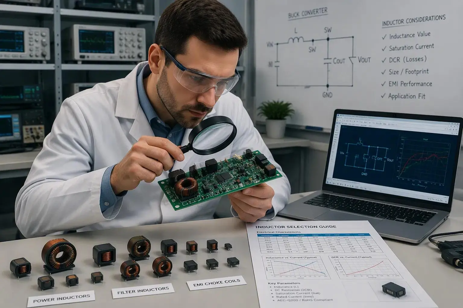
Power, Filtering, and EMI Use Cases
Different applications pull the same parameter set in different directions. The table below maps common use cases to their primary and secondary priorities.
Application | Priority Parameter | Secondary Focus |
Power (DC-DC) | Current (Isat/Irms) and low DCR | Shielding for EMI |
RF / Wireless | High SRF and Q-factor | Tight tolerance |
EMI Filtering | Impedance at noise frequency | Shielding |
Automotive electronics reward low DCR, low loss, high current capability, and EMC compliance. Gujing recommended the GSHM1265MT2R2-V inductor for a seat controller project, and the part met both the current and EMC requirements. The company now supplies samples and mass production for that program. Drone and low-altitude designs balance miniaturization against power delivery. They also demand a wide temperature range and vibration resistance. Gujing's compact inductors carry automotive-grade certification for operation from -40°C to 125°C, and they resist strong vibrations, which suits complex scenarios such as plateau operation. Solar charging controllers prioritize parameter consistency. Gujing addressed poor consistency in that segment by physically testing and matching parameters to ensure uniformity.
From Application Needs to a Clear Spec
A structured workflow turns application needs into a verifiable specification. The sequence below reflects the process Gujing applies to each gujing custom inductor request.
1. Define circuit requirements: maximum continuous current, peak transient current, and operating frequency.
2. Choose the inductance value from the IC datasheet, targeting ripple current at 20%–40% of maximum output current.
3. Estimate current ratings by computing absolute peak current, which equals load current plus half of ripple current, to set the Isat requirement.
4. Check DCR and efficiency, selecting the lowest-DCR option to minimize I²R heat losses.
5. Select the package and verify layout, confirming the footprint fits the PCB and provides adequate copper for heat dissipation.
6. Verify SRF, ensuring it sits well above the operating frequency so the part behaves inductively.
Several rules of thumb sharpen the resulting numbers. Isat should exceed peak current by 30%, and Irms should exceed continuous load by 20%. SRF should exceed ten times the operating frequency. Ignoring these margins invites core saturation, overheating, or a part that behaves capacitively and fails to filter.
Simulation can narrow the field before hardware validation. Engineers define boundary conditions first: output power, input voltage range, switching frequency, ripple constraints, and ambient temperature. A system-level design tool then configures the controller and topology, and a component-level simulation tool tests candidate inductors under those conditions. The comparison covers losses and temperature rise across parts with similar inductance and current ratings but different core materials or geometries. Simulation shortlists options for bench testing, and design refinement may sweep current or frequency to check worst-case margins.
Two controls protect the transition to volume. Sample verification confirms that the prototype meets the specification under real conditions. Two-way sealing then guarantees that mass-produced products match approved samples, so shipping consistency holds for reliable circuit performance. The RFQ should also list RoHS compliance as a specification item, alongside the electrical limits. Gujing's selection process weighs magnetic flux density, permeability, core loss, and Curie temperature together with efficiency, current levels, EMC compliance, and cost. That multi-dimensional view keeps each gujing custom inductor matched to its application rather than to a catalog average.
Seven parameters carry the order: inductance and tolerance, DCR, rated and saturation current, SRF, temperature coefficient and range, and core losses. A clear, balanced specification remains the foundation of a successful OEM/ODM order.
The RFQ should record test conditions and measurement methods beside each limit. Acceptance numbers must match the conditions written on the purchase order, since permeability measured at one frequency, field strength, and temperature does not equal a reading taken elsewhere. Buyers should also mark each requirement as must-have or negotiable.
Confirm definitions with the manufacturer before release, including the saturation current criterion and the DCR test temperature. Validate the approved sample before mass production. Finally, review the spec for each gujing custom inductor against the application, not against a catalog part.