English
 Vietnamese
 Italian
 Spanish
 Thai
 Japanese
 Portuguese
 Korean
 Russian
 French
 German
 Polish
 Indonesian
Solving Automotive EMI Issues Using High-Reliability Common Mode Inductors
Electromagnetic interference in automotive electronics degrades performance, threatens safety, and blocks EMC compliance. The global noise suppression components market, valued at USD 27.88 billion in 2025, reflects the automotive industry's urgent need for effective EMI solutions. High-reliability common mode inductors provide the proven fix. These components attenuate common mode noise while passing differential signals with minimal loss. An introduction to common-mode chokes reveals their critical role in modern vehicle electronics. How should engineers select, apply, and lay out these inductors to meet automotive-grade reliability and EMC standards? The answer determines whether a design passes certification or fails.
Key Takeaways
· Common mode inductors reduce electromagnetic interference in vehicles. They block unwanted noise while letting signals pass.
· Choose inductors that match your circuit's current and noise frequency. Automotive-grade parts handle extreme temperatures and vibrations.
· Place the inductor close to the noise source. Keep input and output traces apart to avoid coupling.
· Test your design early with pre-compliance checks. This saves time and money before full certification.
· Common mode inductors offer a reliable, cost-effective solution for automotive EMI. They help meet EMC standards without overdesign.
How Common Mode Noise Creates EMI in Vehicles
Common mode noise is unwanted current that flows in the same direction on both signal or power lines, referenced to chassis ground. This type of noise stands as a leading cause of electromagnetic interference in automotive systems. Engineers must understand its origins and behavior to design effective suppression strategies.
Sources of Common Mode Noise
Switching DC-DC converters, onboard chargers, motor drives, and PWM controllers generate significant common mode noise in electric vehicles. High-speed data lines such as CAN, LIN, and Ethernet also contribute to this problem. These sources produce noise spanning from 10 kHz to 200 MHz. Fast rise-time waveforms, such as 300V pulses with rise times around 100ns, create harmonics that extend to 10MHz or more. Ignition noise from spark plugs adds another layer of interference in conventional vehicles. Differential-to-common-mode conversion occurs when imbalances in circuit paths transform desired differential signals into unwanted common-mode signals. This conversion amplifies the challenge for automotive electronics designers.
How Common Mode Inductors Suppress Noise
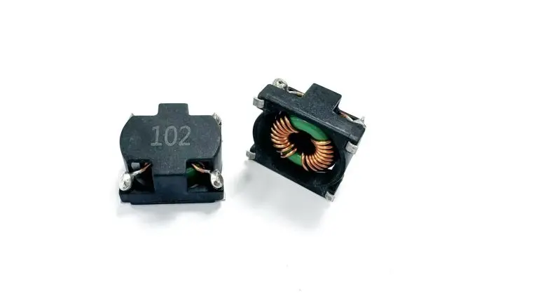
A common mode inductor uses two windings on a shared magnetic core. The windings are wired so differential current cancels flux within the core. Common mode current, however, sees high impedance from the inductor. This behavior provides effective attenuation of the noise to be suppressed without distorting the desired signal. Common mode chokes excel at this task because they target the specific noise path while allowing clean signal transmission. Gujing's Common Mode Inductors, including the GCM Series, GUU 10.5 Series, and GUU Series, are engineered for this exact role in automotive electronics. These components deliver reliable noise attenuation and support filtering requirements across demanding vehicle applications. Designers rely on common mode chokes to meet stringent EMC standards. The operating principle ensures that common-mode currents face opposition while differential data passes freely. This selective filtering capability makes common mode chokes indispensable for modern automotive EMI control. Engineers who select the right common mode inductor achieve stable performance and regulatory compliance.
Selecting the Right Common Mode Inductor
Component selection determines whether an automotive design meets its EMC targets or fails in the chamber. Engineers must weigh several parameters together, because a part that excels in one area often compromises another.
Key Electrical Parameters
The rated current must withstand the maximum continuous operating current of the circuit. This rating depends on allowable temperature rise, placement, and ventilation. The common mode impedance should peak at the target noise frequency, which often falls in the tens to hundreds of megahertz range. Differential mode impedance should stay low so the component does not attenuate useful signals. Lower DC resistance reduces power loss and temperature rise, though winding resistance that is too low can weaken high-frequency damping. Engineers also evaluate saturation behavior and physical size against the available board area.
A common mode choke with appropriate inductance is a common starting point for EMI suppression. Performance verification relies on standard EMC measurement techniques to confirm attenuation and signal integrity across the working band. The table below shows typical automotive-grade targets.
Parameter | Value |
Component Type | AEC-Q200 Common-Mode Chokes (Automotive Grade) |
Rated Current | Up to 14 A |
DCR | Down to 0.4 mΩ |
Impedance | Up to 11 kΩ at 100 MHz |
Application | Automotive power and data systems |
Reliability and Qualification Standards
Automotive electronics demand components that survive harsh conditions. High-reliability inductors must withstand -55°C to +165°C and resist mechanical vibration and shock. Thermal cycling stresses the core and winding, while road vibration tests the mechanical joints. A part that drifts in inductance over temperature will weaken filtering when the vehicle needs it most.
Qualification standards separate automotive-grade parts from commercial ones. AEC-Q200 defines the stress-test requirements for passive components. IATF 16949 and ISO 9001 certify the manufacturing process itself. Gujing brings extensive inductor expertise to this challenge, along with a wide range of magnetic core material options. The company runs highly automated production, which delivers consistency and full traceability across every lot.
The design and selection of common-mode chokes rewards careful matching between the noise profile and the component. A choke with high common mode impedance at the wrong frequency does nothing for interference. Engineers who verify saturation margins and thermal derating early avoid costly redesigns later. The right part balances electrical performance, mechanical durability, and qualified manufacturing in one package.
Implementing EMI Filtering in Circuit Design

Common mode chokes are preferred for well-defined, narrow-band noise with high current requirements and budget constraints. They offer a cost-effective path to compliance when the noise profile is understood. Engineers who apply common mode chokes correctly achieve reliable EMI filtering without overdesign.
Circuit Placement and Filter Topology
Placement determines how well common mode chokes perform. The choke should sit as close as possible to the noise source or connector. This placement prevents noise from coupling onto nearby traces before attenuation occurs. Input and output traces must remain separated to avoid parasitic coupling that bypasses the filter. Sensitive signals should never route near the choke, because radiated fields from the component can induce interference on adjacent lines.
The design and selection of common-mode chokes also depends on topology. A single-stage filter may suffice for mild noise, while severe differential-to-common-mode conversion requires multi-stage filtering. Differential-to-common-mode conversion occurs when trace imbalances transform desired signals into unwanted common-mode signals. This conversion undermines even well-placed chokes. Engineers should verify that the chosen topology addresses both common mode currents and differential mode noise. Common mode currents flow on both lines in the same direction, and the choke presents high impedance to them. Common mode noise from switching supplies often demands this targeted approach.
Gujing offers customization services to support layout-specific needs. These services include application analysis, magnetic material selection, structural design, prototype preparation, and performance verification. Engineers can tailor EMI mitigation solutions to their exact circuit requirements.
PCB Layout Best Practices
PCB layout directly affects filtering effectiveness. Minimizing loop area reduces the antenna effect that radiates high-frequency noise. Ground planes provide a low-impedance return path and shield sensitive traces from stray fields. Differential pairs should remain tightly coupled along their entire length. This coupling preserves signal integrity and reduces the chance of differential-to-common-mode conversion.
In switching supplies, engineers must reduce output voltage ripple and high-frequency noise at the source. Common mode chokes alone cannot compensate for poor layout. The applications of common-mode chokes extend across onboard chargers, DC-DC converters, and battery management systems. Each application demands careful attention to trace routing and component placement.
Common-mode chokes handle high currents and broad noise spectra effectively. The common mode inductor selected for a given design must match the noise frequency and current profile. Common mode chokes provide predictable attenuation when layout rules are followed. Filtering performance improves when engineers treat the choke as part of a complete EMI filtering strategy. This strategy includes proper grounding, shielding, and trace discipline. Common-mode chokes remain central to automotive EMI filtering because they address the root cause of conducted noise. The electromagnetic interference challenges in modern vehicles require this systematic approach.
Engineers who master placement and layout achieve compliance faster. Common mode chokes deliver results when integrated thoughtfully into the PCB.
Comparing Common-Mode Chokes with Alternatives
Engineers face a crowded field of noise suppression options. Each alternative solves a specific problem, and each carries trade-offs that affect cost, size, and reliability.
Ferrite Beads and Capacitors
Ferrite beads and common-mode chokes serve different noise profiles. A ferrite bead suits low-current, high-frequency narrow-band issues. Common mode chokes handle higher currents and broader noise spectra. A bead saturates quickly under heavy current, which collapses its impedance. A choke built on a ferrite core with dual windings maintains performance under load. This difference matters in power lines where current reaches several amperes.
Capacitors offer a cheap path to noise reduction. Their impedance falls as frequency rises, which limits their reach at the upper end of the spectrum. A capacitor alone cannot suppress high-frequency noise across a wide band. Shielding blocks radiated interference effectively, yet it adds weight and cost to every vehicle. Automakers count grams, and shielding works against that goal. Passive EMI filters such as common mode inductors remain highly reliable across temperature and vibration. Their drawback is size and weight, which designers must budget for early.
Shielding and Rod Core Chokes
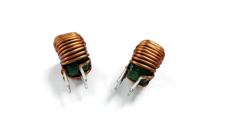
Rod core chokes provide a compact answer for demanding layouts. A rod core delivers high common-mode and differential-mode inductance without saturating. This behavior makes rod core chokes attractive where board space is tight and currents run high. Common-mode chokes still win when the noise band is well defined and the current requirement is moderate.
Differential-to-common-mode conversion complicates every comparison. Trace imbalances transform clean differential signals into unwanted noise, and no single component erases that effect. Engineers who understand differential-to-common-mode conversion choose filtering components that match the actual noise path. Common mode chokes target that path directly. Common-mode chokes also tolerate the wide thermal swings of automotive duty. Common mode chokes deliver predictable attenuation when the noise source and frequency are known. Common-mode chokes cost more than a capacitor but less than a full shielding redesign. The right choice depends on current level, noise bandwidth, and available space.
Validation Checklist for Automotive EMI Design
Pre-compliance testing catches problems before formal certification. Engineers who validate early save time and money. A structured checklist keeps the process on track.
Pre-Compliance Testing Steps
Engineers must measure common mode and differential mode noise separately. This separation reveals which noise path dominates and guides filter design. Two methods serve this purpose.
Method | Equipment | How CM/DM Separation Works |
Dual-LISN with oscilloscope math/FFT | Two LISNs, separate oscilloscope channels | Adding signals in phase cancels differential mode and yields common mode; subtracting them cancels common mode and yields differential mode |
Dual-LISN with characterized combiner and receiver | Dual-LISN setup plus combiner such as TekBox TBLM2, paired with spectrum analyzer | The combiner acts as a dedicated separator; isolated components come from respective outputs |
A spectrum analyzer may be used, but an oscilloscope can provide comparable results if a spectrum analyzer is unavailable. Oscilloscopes with built-in math functions can directly compute common mode and differential mode noise. The oscilloscope channel must be 50 Ohm terminated. The oscilloscope noise floor will be higher than that of a spectrum analyzer. With either instrument, the peak maximum should be used rather than average or quasi-average values.
Engineers then sweep the frequency range and verify performance using the appropriate measurement methods. Signal integrity is confirmed through additional testing. These steps ensure that common-mode chokes perform as expected before vehicle installation.
In-Vehicle Verification Tips
Real-world conditions test components beyond laboratory settings. Engineers must test across the full -55°C to +165°C range. Vibration and shock profiles simulate road conditions. Confirmation in onboard chargers, DC-DC converters, BMS, and ECUs validates performance in actual applications.
Choosing high-precision, high-reliability common mode inductors simplifies EMC design and improves product qualification rates. Common-mode chokes that meet AEC-Q200 requirements reduce redesign cycles. Common mode chokes with stable inductance over temperature maintain filtering effectiveness. Engineers who select qualified components avoid costly delays.
Engineers who match frequency range, rated current, inductance, and size to the noise profile gain dependable EMI suppression. Automotive-grade parts survive extreme automotive temperatures. Early integration pays off. AEC-Q200 qualification keeps common mode chokes stable across every lot. Designers should review current layouts, consult datasheets for automotive-grade common mode chokes, and run pre-compliance tests before full EMC certification. Common mode chokes simplify EMI filtering decisions. Common mode chokes reduce conducted interference, aiding filtering. Common mode chokes deliver predictable attenuation when the noise path is known. A well-chosen common mode inductor answers the core question: how to meet automotive EMC standards without overdesign. Common mode chokes reward early review.
FAQ
What makes a common mode inductor suitable for automotive EMI suppression?
A suitable part attenuates common mode noise while passing differential signals with minimal loss. Engineers match the common mode impedance peak to the target noise frequency. Rated current must cover the circuit's maximum continuous load. Common mode chokes designed for automotive applications target these requirements.
How do common mode chokes handle extreme under-hood temperatures?
Automotive-grade common mode chokes must withstand extreme temperatures. Thermal cycling stresses the core and winding, so stable inductance over temperature keeps filtering effective. Parts that drift weaken noise attenuation when the vehicle needs it most. AEC-Q200 qualification verifies this thermal durability.
Which standards qualify a common mode inductor for vehicle use?
AEC-Q200 defines the stress-test requirements for passive components. AEC-Q200 qualification verifies the component's reliability for automotive use. This delivers consistency and full traceability across every lot.
When should engineers choose common mode chokes over ferrite beads?
Common mode chokes handle higher currents and broader noise spectra. Ferrite beads suit low-current, high-frequency narrow-band issues, but they saturate quickly under heavy load. A common mode choke with appropriate inductance is a common starting point. Chokes also tolerate the thermal swings of automotive duty.
How does a common mode inductor reduce emi without distorting signals?
Two windings share one magnetic core. Differential current cancels flux inside the core, so the desired signal passes freely. Common mode current sees high impedance instead. This selective behavior suppresses emi at its source path. Engineers verify results using appropriate measurement techniques.