
 English
 Vietnamese
 Italian
 Spanish
 Thai
 Japanese
 Portuguese
 Korean
 Russian
 French
 German
 Polish
 Indonesian

 Company Profile
 News
 Success Stories
Two inductors can have nearly identical DC resistance, the same nominal inductance, and a similar package size, yet behave quite differently after operating under sustained current. This distinction became important during a customer's component sourcing project, where a revised 6.8 µH power inductor was evaluated against an alternative sample from another supplier.
The customer was working on a promotional product with strict component cost targets. Suzhou Gujing Electronics developed the GNR6020MT6R8-T as a modified version of the existing GNR6020MT6R8, using an adjusted magnetic material system to meet the project's commercial requirements. Meanwhile, the customer was evaluating a second supplier and requested a direct technical comparison between the two candidates.
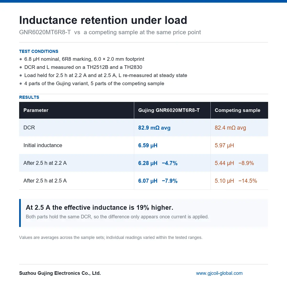
Initial DC resistance measurements suggested little difference between the samples. However, a 2.5-hour loading test revealed a more meaningful distinction. At 2.5 A, Gujing's GNR6020MT6R8-T retained an average inductance of 6.07 µH, while the competing sample measured 5.10 µH.
The difference was approximately 19% in favor of the Gujing sample under the reported test conditions.
This power inductor load testing case illustrates why component selection should consider more than nominal inductance and DCR, particularly when a design must balance sourcing requirements with electrical performance.
Why Did the Customer Need a Different Power Inductor?
The project began with a sourcing challenge rather than a reported electrical failure. The customer had an existing inductor reference, GNR6020MT6R8, but was preparing a promotional product with tighter component procurement requirements.
The engineering objective was to identify a commercially suitable alternative without overlooking the electrical characteristics that mattered to the circuit.
Gujing proposed GNR6020MT6R8-T, a derived version developed through adjustments to the magnetic material system. The revised component retained the 6.8 µH nominal inductance class and 6.0 × 2.0 mm footprint specified for the comparison.
At the same time, the customer had started evaluating a second source. This introduced an additional question: if two candidates appeared similar in their basic specifications, how could the engineering team determine whether their performance would remain comparable during operation?
A datasheet comparison could provide an initial answer about package dimensions, nominal inductance, resistance and current ratings. It could not fully establish how these particular samples would behave after an extended period of electrical loading.
That distinction mattered because the customer's decision involved more than replacing one part number with another. A successful component substitution needed to satisfy the project's sourcing constraints while remaining appropriate for the electrical conditions of the intended design.
The test therefore focused on two practical measurements: DC resistance of power inductors and inductance retention under sustained current.
The first measurement established whether the candidates had comparable winding resistance. The second investigated whether their inductance values changed differently after prolonged loading.
This approach provided a more useful basis for component assessment than relying on nominal specifications alone.
Why Can Two Inductors Have Similar DCR but Different Load Performance?
DC resistance, commonly abbreviated as DCR, measures the resistance of an inductor's winding to direct current. It is an important electrical parameter because winding resistance contributes to conduction losses.
For a given winding resistance, resistive power dissipation increases approximately with the square of the current. DCR can therefore influence the thermal behavior and efficiency of a power conversion circuit.
However, DCR does not independently describe the complete magnetic performance of an inductor.
Inductance depends on several additional factors, including magnetic core material, core geometry, effective permeability, winding arrangement and magnetic operating conditions.
Two inductors with similar resistance may use different magnetic materials or construction methods. Those differences can affect how their inductance responds to current, temperature and magnetic flux.
In particular, inductance drop under DC bias is an important consideration for many power inductors.
As direct current flows through a winding, it establishes a magnetic field within the core. Depending on the material and magnetic circuit design, increasing current may reduce the core's effective permeability, causing the measured inductance to decrease.
The extent of this reduction depends on the component design and test conditions. It cannot be predicted accurately from DCR alone.
Temperature also deserves attention. Extended operation may change winding resistance and magnetic material characteristics as the component approaches thermal equilibrium. The resulting inductance behavior may involve both magnetic bias and temperature-dependent effects.
For this reason, inductor saturation characteristics and thermal performance should be assessed separately from winding resistance.
The Gujing comparison illustrates this principle through measured samples rather than an idealized calculation.
| Electrical factor | What it indicates | Why it matters during sourcing |
|---|---|---|
| Nominal inductance | Inductance under specified reference conditions | Establishes the basic component requirement |
| DC resistance | Resistance of the winding | Influences conduction loss and heating |
| Inductance retention | Remaining inductance after a defined operating test | Helps evaluate performance stability |
| Magnetic core material | Material response to magnetic field and temperature | Can affect inductance behavior under load |
| Current rating | Manufacturer-defined operating or saturation limit | Requires checking the associated rating criteria |
| Temperature behavior | Electrical changes associated with operating temperature | Important for sustained operation |
These parameters are related, but they are not interchangeable.
A low-DCR component is not automatically the component with the highest inductance retention. Similarly, a component with a suitable nominal inductance may require additional evaluation before it can be accepted for a current-intensive application.
That is why Gujing did not stop after establishing that the winding resistance measurements were close.
How Was the GNR6020MT6R8-T Compared With the Competing Sample?
The comparative evaluation involved Gujing's GNR6020MT6R8-T and a competing component supplied for the customer's second-source assessment.
Both candidates belonged to the same nominal inductance class, making them suitable for a focused comparison within the customer's selection process.
The test arrangement was based on the following reported conditions:
| Test item | Recorded condition |
|---|---|
| Gujing model | GNR6020MT6R8-T |
| Nominal inductance | 6.8 µH |
| Component marking | 6R8 |
| Package footprint | 6.0 × 2.0 mm |
| DCR measurement equipment | TH2512B |
| Inductance measurement equipment | TH2830 |
| Sustained loading duration | 2.5 hours |
| Evaluated current levels | 2.2 A and 2.5 A |
| Gujing sample quantity | 4 components |
| Competing sample quantity | 5 components |
The reported evaluation included initial inductance measurements and additional measurements associated with the 2.2 A and 2.5 A loading conditions.
The parts were subjected to extended electrical loading, with inductance evaluated after the specified duration and stabilization.
Using the same general test conditions was important for making the results meaningful. A difference between samples would be difficult to interpret if the applied current, measurement timing or measurement method varied substantially.
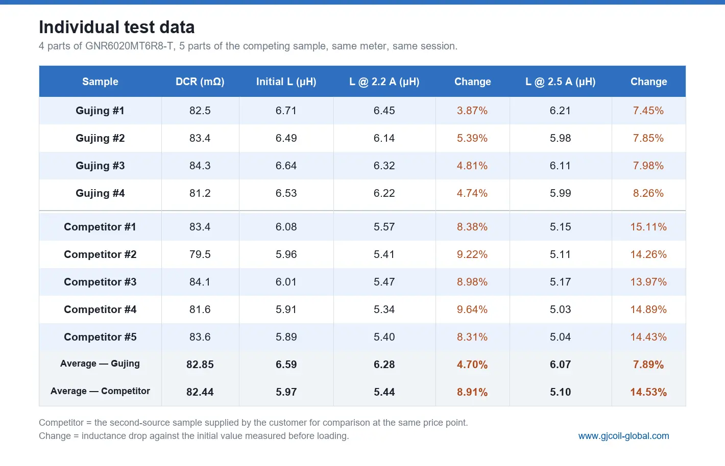
The supplied test summary reports average measurements for each sample group. Gujing tested four components, while the competing group contained five.
This is a limited engineering sample comparison rather than a statistical qualification of entire production lots. Nevertheless, it provides useful evidence about the tested candidates under the documented conditions.
The customer was not trying to prove that every inductor from one manufacturer would outperform every alternative. The immediate objective was narrower: determine whether the proposed GNR6020MT6R8-T offered a suitable electrical response compared with the competing sample.
The GNR6020MT6R8-T inductance test was therefore structured around directly measurable parameters rather than general product claims.
DC Resistance Measurements
The first part of the comparison examined the resistance of the two samples.
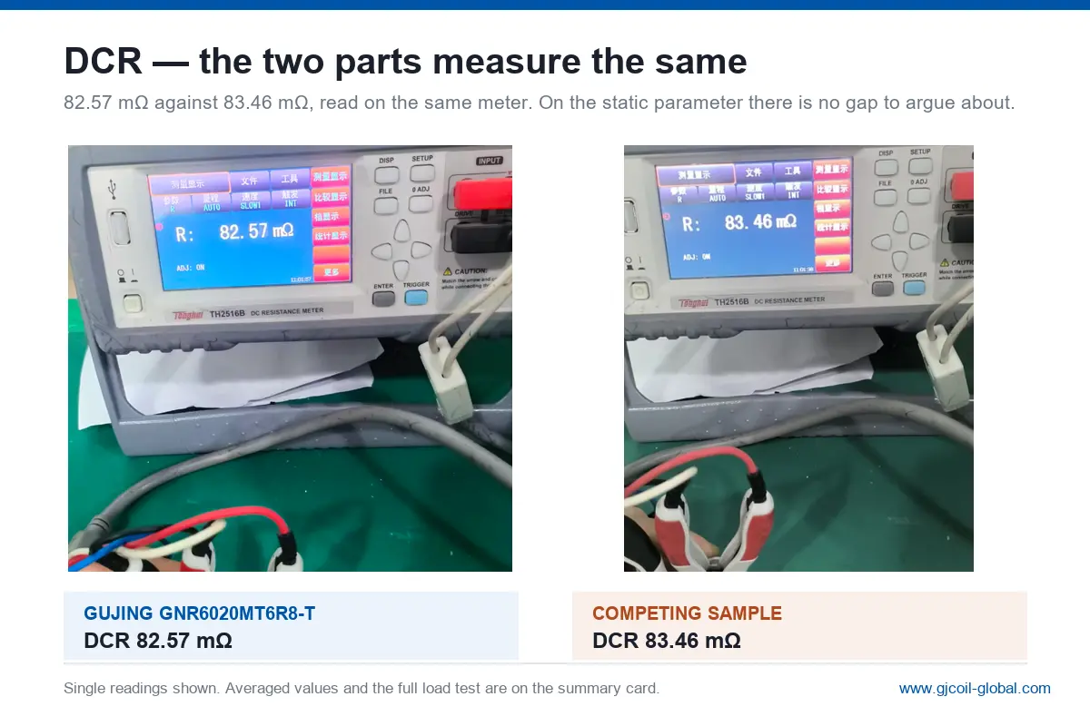
The average DCR reported for the Gujing group was 82.9 mΩ, compared with 82.4 mΩ for the competing group.
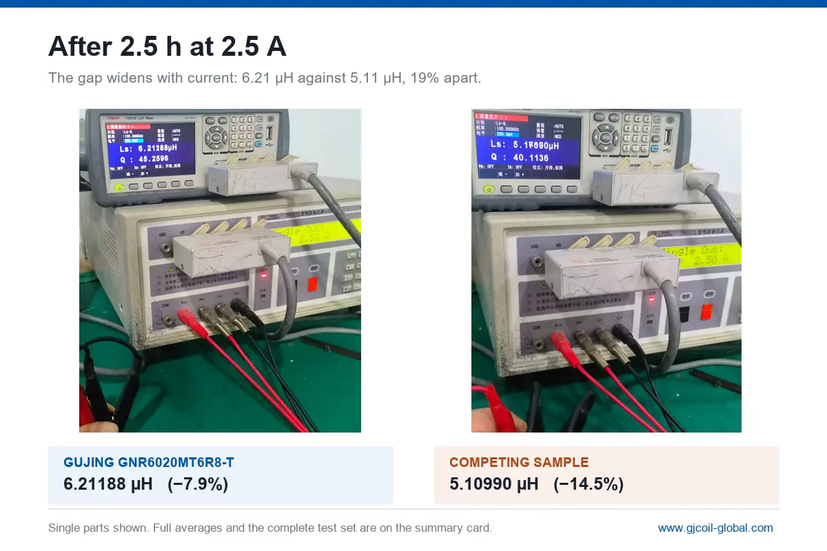
The accompanying instrument photographs also showed individual readings of 82.57 mΩ and 83.46 mΩ.
These photographs provide a visual record of individual measurements, while the summary data represent averages across the tested sample groups. The individual readings should not be confused with the group averages.
The difference between the reported average resistance values was only 0.5 mΩ, approximately 0.6% relative to the competing sample's average.
This meant the test did not reveal a substantial DCR advantage for either candidate.
From a sourcing perspective, that was an important result. It established that both sample groups had broadly comparable winding resistance, allowing the customer to focus more closely on their different inductance behavior.
What Happened After Two and a Half Hours of Continuous Loading?
The most significant findings appeared in the inductance measurements associated with sustained loading.
Before the extended current test, Gujing's GNR6020MT6R8-T recorded an average initial inductance of 6.59 µH. The competing sample group recorded 5.97 µH.
Both were being assessed as 6.8 µH nominal components, but their measured starting values were not identical.
This difference should be recognized when interpreting the later results. A comparison of final inductance alone would not fully distinguish between a higher initial value and a smaller percentage reduction during loading.
The test summary therefore provides both the measured inductance values and their percentage changes.
| Parameter | Gujing GNR6020MT6R8-T | Competing sample |
|---|---|---|
| Average DCR | 82.9 mΩ | 82.4 mΩ |
| Initial inductance | 6.59 µH | 5.97 µH |
| After 2.5 hours at 2.2 A | 6.28 µH | 5.44 µH |
| Inductance change at 2.2 A | −4.7% | −8.9% |
| After 2.5 hours at 2.5 A | 6.07 µH | 5.10 µH |
| Inductance change at 2.5 A | −7.9% | −14.5% |
Source: Gujing comparative engineering test summary, November 6, 2026. Values are reported averages for the tested sample groups.
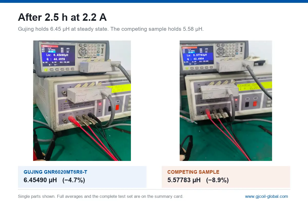
At 2.2 A, the Gujing sample group retained an average inductance of 6.28 µH, representing a reduction of approximately 4.7% from its initial value.
The competing group recorded 5.44 µH, corresponding to a reduction of approximately 8.9%.
This difference became more pronounced at the higher evaluated current.
At 2.5 A, Gujing's average inductance decreased to 6.07 µH, while the competing group's average declined to 5.10 µH.
The percentage reductions were approximately 7.9% and 14.5%, respectively.
In absolute terms, the Gujing sample's inductance was 0.97 µH higher at the end of the reported 2.5 A evaluation.
Relative to the competing sample's 5.10 µH result, the Gujing value was approximately 19% higher.
This was the central finding of the customer's inductor performance comparison under load.
The two candidates had similar average DCR values, but their inductance measurements after sustained loading were noticeably different.
The percentage reductions also showed that the Gujing sample retained a larger proportion of its own initial inductance.
At 2.5 A, the reported values corresponded to approximately 92.1% retention for Gujing and 85.5% for the competing group.
These findings gave the customer additional evidence for assessing the GNR6020MT6R8-T against the competing second-source candidate.
They did not, by themselves, establish the cause of the difference or demonstrate the same performance relationship under every possible operating condition.
How Did the Magnetic Material Adjustment Influence the Design?
The defining engineering change behind the GNR6020MT6R8-T was an adjustment to the magnetic material system.
This decision was made during the development of a more commercially suitable variant of the existing GNR6020MT6R8.
The magnetic core is a major contributor to the electrical characteristics of an inductor. Its composition, permeability and response to magnetic field strength influence the relationship between winding current and inductance.
In a practical design, changing the core material may alter several characteristics simultaneously.
For example, a revised material system may affect initial inductance, DC bias response, temperature behavior and core losses. The final results also depend on the component's winding and magnetic circuit design.
These interactions make magnetic material selection more complex than choosing a material based on a single property.
A design focused only on maximizing initial inductance might not provide the most suitable behavior at operating current. Conversely, improving current handling may introduce other trade-offs that need to be considered.
For the GNR6020MT6R8-T project, the test results demonstrated that the revised sample maintained relatively strong inductance retention under the evaluated loading conditions.
However, the available test records do not isolate the magnetic material adjustment as the sole cause of the difference between the two suppliers.
The competing sample's exact magnetic composition, construction details and manufacturing conditions were not included in the supplied summary.
It would therefore be inaccurate to claim that a specific core composition directly caused the measured performance advantage.
What the comparison does establish is that the completed Gujing design achieved higher measured inductance after the stated load tests.
This distinction is important for engineering credibility.
A credible custom magnetic material power inductor development case should connect material decisions with measurable electrical outcomes without overstating what the available data can prove.
For customers considering custom inductors, this also highlights the importance of discussing operating conditions during development.
If a component must carry a particular current for an extended period, the manufacturer should know that requirement before finalizing the magnetic design.
The selection process can then consider the current profile, required minimum inductance, package limitations and thermal environment together.
What Do the Results Mean for DC DC Converter and Power Supply Design?
Inductors are used in many power electronic circuits to store energy, filter current and manage ripple.
In switching converters, inductance influences how quickly current changes during the switching cycle. Depending on the converter topology and operating mode, a reduction in effective inductance may increase ripple current and alter electrical stresses.
This makes effective inductance at operating current a more useful design consideration than the nominal value alone.
For example, an engineer selecting a component for a compact DC-DC converter may begin with a required nominal inductance and available PCB footprint.
The shortlist may then be narrowed by DCR, current rating, temperature limits and component dimensions.
However, if two candidates show similar nominal parameters, an additional comparison of inductance under realistic operating conditions may reveal differences that were not obvious from the initial selection.
The Gujing test demonstrates such a situation.
Although the candidates had nearly equal average DCR values, the measured inductance after extended loading differed by 0.97 µH at 2.5 A.
That difference may be relevant to a circuit where inductance retention is a critical design consideration.
Its actual impact on converter efficiency, output ripple, temperature or stability would still need to be established through application-specific circuit testing.
The supplied customer case does not include measurements of converter output ripple, system efficiency or finished-product reliability. It would therefore be inappropriate to claim specific system-level improvements from the component comparison alone.
Nevertheless, the results help explain why high current SMD power inductor selection often requires examining the current-dependent magnetic behavior of a component.
The same principle can be relevant to industrial control equipment, electronic power modules and other applications that use inductors in current-carrying circuits.
The required test conditions will vary between applications. A circuit with short current pulses may need a different evaluation from one that operates near a steady current level for long periods.
Engineers should therefore define the operating current profile before deciding which component measurements are most useful.
For this project, the sustained 2.2 A and 2.5 A comparisons provided a practical starting point for evaluating the proposed replacement.
Why Is a Two and a Half Hour Load Test Useful but Not Sufficient on Its Own?
A short measurement at room temperature can establish a component's initial electrical characteristics.
It does not necessarily describe what happens after the component has been operating for an extended period.
A sustained load test allows engineers to observe electrical behavior after an extended interval at the selected current.
This is especially useful when evaluating components intended for circuits with significant continuous current.
During such testing, winding temperature and magnetic material behavior may change as the component operates. The resulting measurements can provide additional insight into performance beyond the initial datasheet values.
In this case, the 2.5-hour evaluation provided comparative evidence that the GNR6020MT6R8-T retained more inductance than the competing candidate.
However, several limitations should be considered when interpreting the findings.
First, the sample sizes were relatively small. Four Gujing components and five competing components are sufficient for a preliminary comparison but do not establish long-term production consistency.
Second, the test summary reports averages rather than the full individual measurement data. The distribution, measurement uncertainty and variation between samples are not provided.
Third, the supplied material does not include the complete temperature record, ambient conditions or detailed measurement sequence.
As a result, the available information cannot separate the effects of DC magnetic bias, temperature and other test-related factors with certainty.
Finally, the test was conducted at two current levels over a defined duration. It does not replace a complete characterization across the intended operating current and temperature range.
A comprehensive qualification plan may include DC bias curves, temperature-rise measurements, electrical tolerance checks, soldering compatibility and repeated production-lot testing.
These additional steps are particularly important when evaluating a new supplier for a production program.
The Gujing results are therefore best understood as a documented comparative engineering assessment.
They show how the tested samples behaved under the stated conditions and provide evidence that can inform subsequent component selection.
How Should Buyers Evaluate a Lower Cost Inductor Replacement?
Component sourcing decisions are often influenced by production targets, supply continuity and opportunities to optimize a bill of materials.
These considerations are legitimate, but an inductor replacement should not be accepted solely because its nominal specifications appear similar.
The customer's project provides a practical example of why the evaluation process should include electrical verification.
The original GNR6020MT6R8 was the starting reference. Gujing developed the GNR6020MT6R8-T as an adjusted-material alternative, while another supplier provided a separate candidate for comparison.
The customer could then review the candidates against both commercial requirements and measured electrical behavior.
A practical power inductor second source qualification process should address the following questions:
Are the basic specifications compatible? The nominal inductance, package dimensions, mounting arrangement and relevant electrical ratings should match the intended application requirements.
How does the inductor behave at the actual operating current? DC resistance and nominal inductance should be supplemented with current-dependent inductance measurements where appropriate.
What happens during sustained loading? Electrical performance should be assessed after operating for a period representative of the intended application.
Are the results consistent across samples? Multiple samples and, when necessary, different production lots should be evaluated before reaching broader conclusions.
Can the supplier support application-specific testing? Clear measurement records and technical communication help engineers understand trade-offs before approving a substitution.
In this project, Gujing's measurement data gave the customer a useful basis for distinguishing between samples that initially appeared similar.
The key finding was not that resistance had been reduced dramatically or that the package had been redesigned. It was that the revised component offered greater inductance retention in the reported sustained-load comparison.
That result could inform the customer's next-stage electrical validation and sourcing decision.
The supplied material does not confirm a final production approval, purchase order or completed mass-production substitution, so those outcomes should not be assumed.
What Can Engineers Learn From the GNR6020MT6R8-T Comparison?
The central lesson of this case is that similar static electrical measurements do not guarantee similar behavior after loading.
The GNR6020MT6R8-T and the competing sample had average DCR values of 82.9 mΩ and 82.4 mΩ. On resistance alone, neither candidate showed a meaningful advantage.
After 2.5 hours at 2.5 A, however, their reported average inductance values were 6.07 µH and 5.10 µH.
This represented approximately 19% higher measured inductance for the Gujing sample, along with a smaller percentage reduction from its initial value.
For the customer, these results provided a more complete picture of the available component options.
For engineers working with SMD power inductors, the case reinforces the need to evaluate the operating current profile rather than relying exclusively on nominal inductance and winding resistance.
For procurement teams, it also shows why commercial alternatives should be compared against defined technical acceptance criteria.
Gujing's role in this project extended beyond providing a replacement part number. The company developed a revised magnetic material variant and carried out a comparative test to support the customer's assessment.
Further application-level and production qualification would still be needed before drawing conclusions about finished-product performance.
Customers planning a power inductor replacement or custom development project can review Gujing's SMD Inductor range, Compatible Inductor solutions and inductor selection support to identify suitable candidates for technical evaluation.
The most useful component choice is not necessarily the one with the most attractive single datasheet value. It is the one whose measured characteristics meet the actual electrical requirements of the application.