English
 Vietnamese
 Italian
 Spanish
 Thai
 Japanese
 Portuguese
 Korean
 Russian
 French
 German
 Polish
 Indonesian
Rod Inductor vs. I-Shaped Inductor: Efficiency & Space Footprint Comparison
Engineers face a clear trade-off when selecting magnetic components. A rod inductor typically delivers higher efficiency and lower cost, yet it occupies a larger footprint. An I-shaped inductor offers a compact footprint with slightly lower efficiency. Neither advantage comes free.
The right choice depends on five practical factors: efficiency targets, available board space, application fit, compliance requirements, and budget. A design with room to spare may favor the rod type, while a densely packed board may favor the I-shaped type.
This comparison examines both power inductor families point by point. It closes with practical selection guidance for power inductors in real designs.
Rod Inductor Efficiency
Core Loss and Saturation
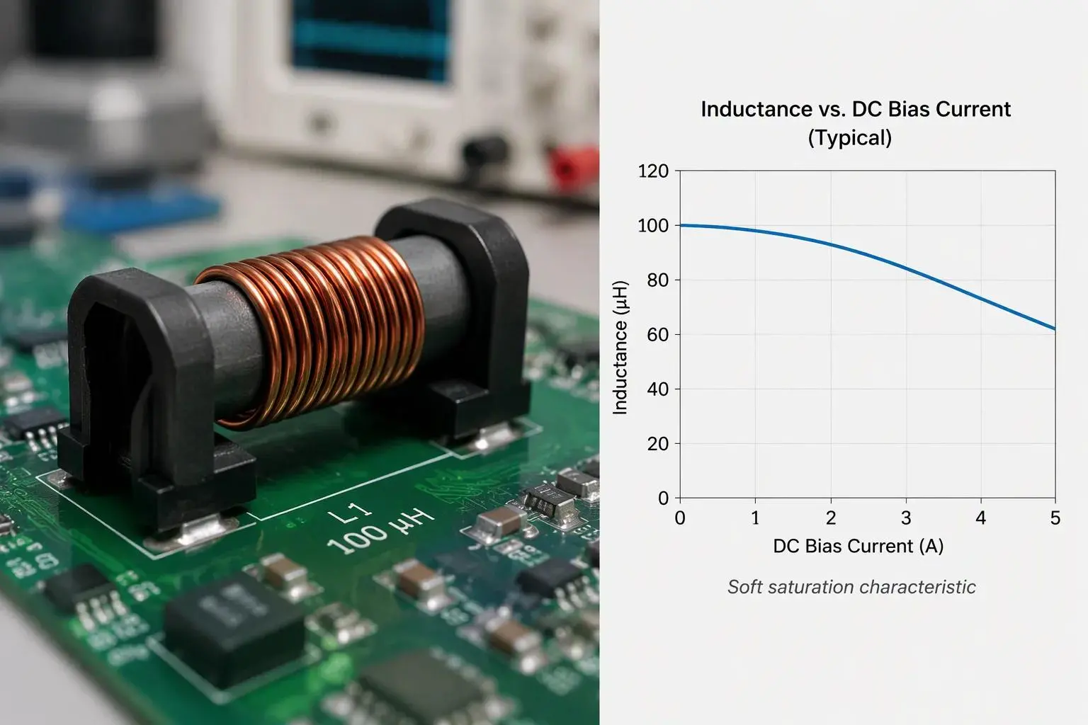
A rod inductor uses an open magnetic structure. The magnetic path runs through the core and returns through air. This open path limits flux density before saturation. Air return path reluctance dominates the magnetic circuit. The result is a soft saturation profile. Inductance falls gradually as current rises. Designers read this behavior on the inductance-versus-dc-bias curve. A gentle slope on the inductance-versus-dc-bias curve gives headroom before saturation. The open structure also lowers core loss at moderate flux. Core material stores energy efficiently with little loss per cycle. Saturation current stays predictable across batches. The inductance-versus-dc-bias curve shifts little from unit to unit. Stable saturation behavior helps switching converters hold regulation. Core loss stays low because core volume is small. This inductor type excels at efficient energy storage. The air path stores energy outside the core. This storage mechanism suits filter chokes and energy-storage roles. Winding geometry sets the flux pattern around the core.
Inductance and Frequency Behavior
Higher inductance stores more energy. The trade-off appears in the winding. More turns enlarge the coil. A larger coil raises dc resistance. Higher dc resistance adds copper loss and erodes efficiency. The designer balances inductance against dc resistance on the inductance-versus-dc-bias curve. A point on the inductance-versus-dc-bias curve shows usable inductance at rated current. Low dc resistance keeps resistive loss small. Low dcr also limits self-heating. The dcr value sets the resistive loss budget. A careful dcr choice preserves converter efficiency. The dcr target depends on current ripple. The dcr figure also interacts with switching frequency. Higher switching frequency allows a smaller inductance value. A smaller inductance value permits fewer turns and lower dcr. Lower dcr then reduces loss. This loop ties inductance, dcr, and switching frequency together. A designer compares candidate parts on the same curve. The comparison shows which part holds its value at peak current.
Switching frequency shapes the loss balance in any power inductor. At low switching frequency, dc resistance dominates. At high switching frequency, core loss rises. The rod type keeps core loss modest across a wide band. Its open structure avoids flux crowding. The part holds stable inductance as switching frequency climbs. Stable inductance simplifies loop compensation. Ripple depends on inductance and switching frequency together. Lower ripple cuts core loss. That reading predicts real saturation margin. The same reading predicts real loss at the operating point. This inductor type delivers low loss in these conditions. Saturation margin shrinks as current climbs toward the knee. The knee marks the onset of saturation. Deep saturation raises loss sharply. Designers avoid deep saturation in normal operation. Core loss and dcr together set the total magnetic loss. Power inductors in this family suit low- to medium-frequency duty. Core loss per cycle falls as switching frequency drops. Core loss rises again at very high switching frequency. Total loss includes core loss and dcr heating. Thermal design follows the same logic. A part with margin runs cooler under load. The thermal budget then closes with room to spare.
I-Shaped Inductor Efficiency
Shielding and Core Losses
An I-shaped inductor winds its coil around a drum core. The drum shape concentrates flux inside the core body. A shield sleeve or potted housing then surrounds the winding. This closed path raises flux density before saturation. The saturation point sits higher than an open rod design of similar size. A higher saturation point lets the part carry more current in a smaller body. Core loss stays controlled because the flux stays inside the magnetic material. Shielding also traps the magnetic field. Radiated emissions drop, and nearby traces pick up less noise. Switching converters benefit from this quieter behavior. The shield adds a small penalty. Shielded cores show slightly higher core loss than open rod cores at the same flux level. The gap matters most at high switching frequency. At low switching frequency, the difference fades. Designers weigh this slight efficiency trade-off against the EMI gain. Many compact designs accept the trade gladly.
DC Resistance Trade-Offs
Winding geometry sets dc resistance in any power inductor. A drum core leaves little room for thick wire. The winding must fit inside the shield. This constraint pushes dcr upward. Higher dcr raises dc copper loss. The dc resistance also adds heat inside a small package. A designer tracks dcr against the current ripple target. Low dcr keeps copper loss small at rated current. The dcr value also interacts with switching frequency. A higher switching frequency allows fewer turns and lower dcr. That change trims dc resistance and copper loss together. The dcr budget still limits how small the part can get. Each candidate part needs a dcr check at peak current. The dcr figure predicts self-heating directly. Saturation margin shrinks as current climbs, so the dcr check belongs beside the saturation check. Power inductors in this family trade a little efficiency for density. That trade fits best where board area and emissions control dominate. The efficiency gap versus rod types stays small in most designs.
Space Footprint and Mounting
PCB Area and Height
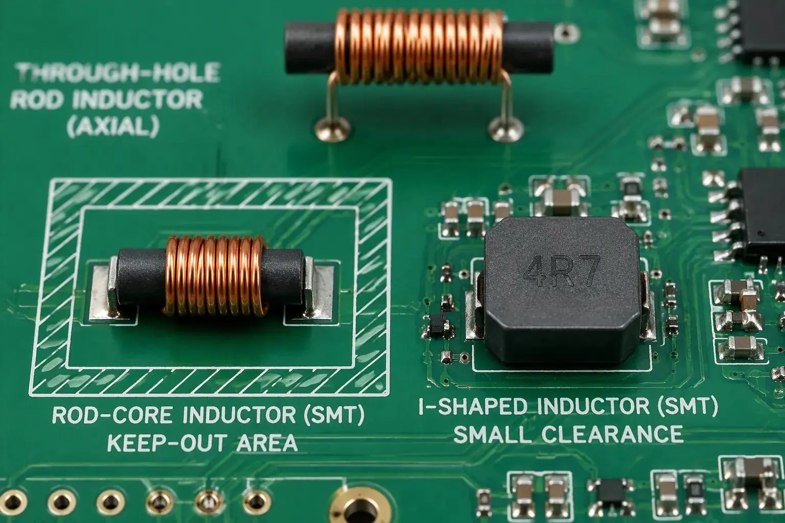
Physical size drives the layout decision as much as electrical performance does. A rod-core choke can reach a target inductance with a smaller core than a closed-core part. The open magnetic structure returns flux through air, so the core body carries less of the magnetic path. This geometry supports efficient use of space at the component level. Height and clearance needs still shape the final layout. An open rod design radiates flux outward, so the designer reserves keep-out area around the part. Nearby traces and shields must sit outside that zone. A shielded I-shaped part contains its field and needs less clearance. The trade runs in both directions. The rod type wins on core volume, and the I-shaped type wins on surrounding clearance.
Horizontal space on a PCB often decides the mounting style. Through-hole rod inductors use long leads and a traditional horizontal rod-type winding. They occupy a larger footprint and suit less dense layouts. SMT rod-core inductors replace those leads with surface-mount end electrodes. The same rod-core winding then fits a smaller footprint and supports high-density PCB designs. Automated SMT assembly also becomes possible.
Aspect | Through-hole rod inductors | SMT rod-core inductors |
Termination | Long through-hole leads | Surface-mount end electrodes (no long leads) |
Footprint | Larger footprint | Smaller footprint compared with traditional through-hole inductors |
PCB design | Less suited to high-density layouts | Suitable for high-density PCB designs |
Assembly | Not compatible with automated SMT | Compatible with automated SMT assembly |
Structure | Traditional horizontal rod-type winding | Same rod-core winding, but with SMT end electrodes |
Radial and Axial Inductors
Lead style shapes how a part sits on the board. Radial and axial inductors cover the two through-hole families. Radial and axial inductors differ in lead exit direction, and each layout favors one. Radial and axial inductors with a vertical body save horizontal space. Radial and axial inductors with a horizontal body keep a low profile. Designers pick among radial and axial configurations to match the enclosure. A side-lead configuration can further trim the outline in tight spaces.
Flat-wire winding improves space utilization inside the part. A flat conductor packs more copper into the same window and raises fill factor. Better fill factor lowers dc resistance for a given winding area. Lower resistance trims copper loss and heat. The winding change does not alter the magnetic path, so inductance stays stable. When space is limited, this construction helps a power inductor meet both the height budget and the loss budget. When space is limited on a crowded board, the mounting choice and the winding choice work together. Power inductors from Gujing support this customization across inductance, wire diameter, core material, winding structure, dimensions, and current capacity.
Power Inductor Application Fit
Power Supplies and Filters
A rod inductor serves two core roles in circuit design. The table below maps each role to its function.
Application Area | Role of Inductor |
Filters | Passes low-frequency signals while blocking others; removes high-frequency noise in radios and audio devices. |
Power Supplies | Smooths and stabilizes current by storing energy at high current and releasing it when current drops, reducing ripple. |
A rod core inductor forms by winding wire around a cylindrical ferrite rod core. This simple construction delivers moderate inductance. The part suits RF and low-frequency operation. Designers find these parts in radio circuits, antennas, and signal filtering. Gujing supplies this family for switching power supplies, industrial control, LED lighting, consumer electronics, communications, appliances, motor systems, automotive, and photovoltaic equipment.
Each application sets its own inductance target. A filter stage needs stable inductance across the band. A supply stage needs enough inductance to hold current ripple low. Saturation margin then decides the current rating. A designer checks saturation at peak load. The saturation point must sit above the worst-case current. Loss then follows from the winding and core. Low loss keeps the part cool. Copper loss rises with dc resistance, so wire gauge matters. Switching frequency sets the ripple amplitude. A higher value shrinks the ripple and eases the inductance requirement. Switching converters in these systems rely on that balance. Gujing customizes inductance values, wire diameter, core materials, winding structures, dimensions, and current capacity for OEM and ODM programs.
EMI and Shielding Needs
An open rod design radiates flux outward. That behavior shapes where the part fits best. Filter chokes in radios and audio devices tolerate the open field. A shielded part contains its field and quiets nearby traces. The designer weighs saturation headroom against clearance. An open part needs keep-out area. A shielded part needs less. Loss stays the deciding factor in both cases. Core loss and winding loss together set the thermal budget. A part with saturation margin runs cooler. The same part holds inductance under load. Gujing builds power inductors for both roles and matches each design to its application.
A power inductor choice starts with the load profile. Peak current sets the saturation requirement. Ripple current sets the inductance floor. Thermal rise sets the loss ceiling. The saturation curve shows where inductance falls. The loss curve shows heating at the operating point. Saturation behavior stays predictable across batches. A part with saturation headroom and low loss meets the brief. The final loss check confirms the thermal budget. Saturation margin then confirms the current rating. Inductance tolerance closes the review.
Compliance and Cost
Safety and Emissions Standards
Certified quality systems serve as a practical selection criterion. A buyer should confirm that a supplier holds IATF 16949 and ISO 9001 registration before awarding a program. IATF 16949 builds on ISO 9001 as a unified automotive quality framework. It adds automotive-specific requirements on top of the general system. Key processes must reach CPK of at least 1.67, with a zero-defect target and a design life generally exceeding 15 years. Product development must follow APQP, and SPC methods must monitor key production parameters. These controls matter because saturation behavior and inductance tolerance shift with process drift. A stable process keeps saturation margin predictable across batches.
Emissions and safety rules also shape the part choice. Automotive programs lean on EMC standards, which push designers toward shielding techniques that suppress interference. RoHS and REACH declarations cover global market access. AEC-Q200 qualification, backed by test reports, covers passive component reliability. The table below groups the common requirements.
Standard or Requirement | What It Covers |
IATF 16949 | Automotive quality management system requirements |
AEC-Q200 | Passive component qualification, supported by test reports |
ISO 9001 / ISO 14001 | General quality and environmental management systems |
RoHS / REACH | Market compliance declarations for global markets |
Unit Cost and Sourcing
Unit price tells only part of the cost story. Total cost of ownership adds assembly time, test yield, and field reliability. EI-core designs offer cost-effectiveness through fast assembly and easy air-gap adjustment. The air gap sets saturation headroom directly, so a quick gap change trims cost without a new tooling cycle. A designer should weigh copper loss and core loss together against the price. A cheaper part with higher loss can raise thermal design cost later. Sourcing stays factual: compare quoted price, lead time, and certification status side by side. A supplier with documented process control and traceability reduces incoming inspection burden. That saving rarely appears on the quote, yet it counts in the total.
Power-Inductor Family Comparison
Side-by-Side Table
The table below summarizes the power-inductor family comparison across five decision factors.
Factor | Rod inductor | I-shaped inductor |
Efficiency and loss | Low loss; stable inductance at rated current; inductance holds at peak | Slightly higher loss; inductance holds under load |
Footprint | Larger footprint; open field needs clearance | Compact footprint; shielded field needs less clearance |
Application fit | Switching converters, filters, LED lighting, motor systems | Dense boards, EMI-sensitive designs |
Compliance | IATF 16949 and ISO 9001 supply base | IATF 16949 and ISO 9001 supply base |
Cost | Lower unit cost | Higher unit cost; lower total cost in dense layouts |
Selection Guidelines
A designer should choose a rod inductor when low loss and cost dominate and the layout allows space. The open structure keeps core loss low and holds inductance stable across the load range. Saturation margin stays predictable, so the part suits switching converters and filter stages. A designer checks saturation at peak current and confirms the dcr budget. Low dc resistance keeps dc copper loss small. The dcr figure also sets self-heating. A part with saturation headroom and low loss meets the thermal brief. Inductance tolerance then closes the review. A tight inductance window protects the current ripple target. A power inductor with margin runs cooler under load. The inductance value also sets the ripple amplitude. Inductance drift stays small across batches. Both families share the same compliance base. A buyer compares quoted price, lead time, and certification status side by side.
An I-shaped part fits best when board area and EMI control are critical. The shield contains the field, so nearby traces pick up less noise. The drum core carries more flux before the knee. The designer still checks dcr at the operating point. Switching frequency shapes the loss balance in both families. Higher frequency trims turns and dcr, which lowers total loss. Inductance stays stable in either family. Each family fits its own role. Power inductors from either family meet the same compliance standards. The final choice follows the application, the compliance needs, and the budget. A designer confirms the inductance target before release. The loss budget then closes. A loss check confirms the thermal margin. The layout then decides the mounting style. Through-hole parts suit low-density boards, and surface-mount parts suit automated assembly. A shielded part needs less keep-out area. An open part needs a wider clearance zone. The final review weighs thermal margin against board area.
The trade-off stays simple. A rod inductor delivers strong efficiency and lower cost when the layout allows room. An I-shaped inductor delivers a compact space profile and tighter EMI control. Each family fits its own role.
A designer should match the power inductor to the application, the compliance needs, and the budget. Rod parts suit switching converters and filter stages where inductance stability and low loss matter most. I-shaped parts suit dense boards where field containment matters. Check inductance at peak current, confirm the loss budget, and weigh copper loss against clearance. Neither family wins everywhere. The right choice follows the design.