 English
 Vietnamese
 Italian
 Spanish
 Thai
Thai Japanese
 Portuguese
 Korean
 Russian
 French
 German
 Polish
 Indonesian
Why Color Ring Inductor Tolerance and DCR Matter for Your PCB
Tolerance and DCR matter because they directly affect circuit accuracy, efficiency, and reliability in PCB assembly. A color ring inductor serves filtering, tuning, and power circuits. These inductors are not interchangeable. An inductor with a loose value shifts frequency response. An inductor with high DCR wastes power as heat. Such inductors cause signal distortion, overheating, and failed assemblies. Every inductor on the board must meet its rated specification. Designers who ignore inductor specs risk costly rework and unstable performance. The right inductor choice prevents these failures. It keeps circuits stable and efficient. Proper selection always starts with understanding both parameters.
Color Ring Inductor Tolerance and Inductance Basics
What Inductance Tolerance Means
Inductance tolerance describes the allowable variation from a nominal inductance value. Manufacturers express this variation as a percentage. A 100 µH inductor with ±10% tolerance may measure anywhere from 90 µH to 110 µH. This range affects how the component performs in a circuit.
Tight tolerance costs more to produce. Loose tolerance saves money but introduces uncertainty. Designers must weigh these tradeoffs for each application.
Common tolerance classifications include M (±20%) and N (±30%). These codes appear on datasheets and component labels. Military-grade inductors achieve much tighter tolerances. Brown indicates ±1%, green indicates ±0.5%, and purple indicates ±0.1%. Regular inductors use gold for ±5% and silver for ±10%.
Gujing's Color Ring Inductor series, including the DLGA0510 and DLGA0410 models, demonstrates consistent tolerance control across production batches. These through-hole inductors suit filtering, energy storage, and signal processing tasks.
Reading Tolerance Bands and Codes
A color coded series of bands communicates inductance value and tolerance on the component body. The reading method depends on band count.
For a four-band inductor, the first two bands are significant digits, the third band is the multiplier, and the fourth band indicates tolerance. For a five-band inductor, the first three bands are significant digits, the fourth band is the multiplier, and the fifth band indicates tolerance.
Consider a four-band example: yellow (4), violet (7), red (×100), gold (5%). This yields 47 × 100 = 4700 µH with 5% tolerance. A five-band example: red (2), violet (7), black (0), brown (×10), gold (5%). This yields 270 × 10 = 2700 µH with 5% tolerance.
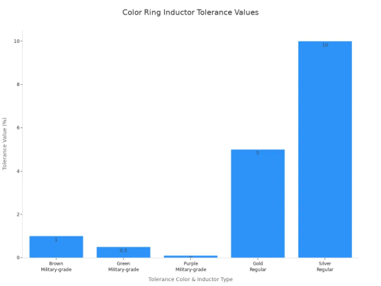
The table below summarizes tolerance color codes for quick reference.
Tolerance Color | Tolerance Value | Inductor Type |
Brown | ±1% | Military-grade |
Green | ±0.5% | Military-grade |
Purple | ±0.1% | Military-grade |
Gold | ±5% | Regular |
Silver | ±10% | Regular |
Reading colored bands correctly prevents assembly errors. A misread tolerance band sends the wrong inductor to the production line.
How Tolerance Impacts Circuit Performance
Filtering and Tuning Accuracy
Inductance value and tolerance shape the frequency response of every filtering and tuning circuit. A filter passes or blocks signals at specific frequencies. That behavior depends on the exact inductance in the circuit. When the actual value drifts from the nominal inductance, the cutoff frequency moves with it. A tuning circuit behaves the same way. The resonant point shifts, and the circuit no longer performs as designed.
Resonant frequency depends on both inductance and capacitance. Any error in either component moves the resonant point. Capacitors commonly vary by about ±5% to ±20%. Inductors frequently vary by ±10% or more. These deviations combine. The actual resonance can land several percent away from the intended value. Precision components or post-assembly adjustment solve this problem. Without them, the circuit drifts.
A practical example shows the scale of the issue. A 1 MHz oscillator built with ±10% components can drift between roughly 950 kHz and 1050 kHz. Communication systems often need kilohertz-level accuracy. This deviation is unacceptable there. Precision RF designs frequently include adjustable tuning components to compensate. Temperature effects make matters worse. Ferrite-core inductors change permeability with temperature. Parasitic resistance in inductors and equivalent series resistance in capacitors reduce the quality factor Q at higher frequencies. That reduction can shift the resonant frequency further.
Tighter tolerance helps, but it comes at a cost. In RF inductors, tolerances such as ±2% to ±5% become difficult to achieve as component size decreases. This limitation affects manufacturing yield and reduces performance stability. It also influences how accurately engineers can tune resonant circuits.
Assembly Yield and Mismatch Risks
Tolerance mismatches create real problems on the production line. Two inductors from the same batch may sit at opposite ends of their tolerance range. One circuit works. The next one fails. This inconsistency drives up rework and scrap rates.
A color ring inductor with a loose tolerance band makes this risk worse. The band tells the assembler the rated range, but not the actual value of that specific part. A board populated with mismatched inductors may pass functional test on one unit and fail on another. Engineers then spend time debugging a problem that stems from component variation, not design error.
Matching tolerance to the application reduces these risks. Tuning circuits need tight tolerance. Filtering circuits often accept looser tolerance. Designers who check the tolerance band against the circuit requirement catch mismatches before production starts. This step protects assembly yield and keeps circuit behavior consistent across every unit.
DCR Effects on Power Loss and Efficiency
DCR, Heat, and Current Rating
DCR is the DC resistance of the inductor's winding. This resistance comes from the copper wire inside the component. A low DCR minimizes power loss and internal heating. The relationship follows a simple rule: dissipated power equals current squared times resistance. Even a few milliohms of winding resistance can produce substantial heat when the inductor carries tens or hundreds of amperes. The loss grows with the square of the current.
Higher DCR means more heat. More heat lowers the safe current rating. A designer who pushes a color ring inductor beyond its rated permissible current may trigger heat generation, magnetic saturation, and efficiency loss. The component may fail. For reliable performance, engineers must consider saturation current, temperature rise, and inductor core material when comparing power inductors for a buck or boost converter.
Component size plays a major role here. SMD inductor size determines DCR, current rating, saturation headroom, and heat management. A smaller package cannot dissipate heat as effectively. It also limits the cross-sectional area of the winding. Flat-wire windings improve conductor packing density. This design allows more conductor cross-sectional area or a more compact winding for a given design. The result is lower DCR and reduced conduction loss. These benefits matter most at high current because conduction loss scales with current squared.
Engineers should review hot DCR, not only room-temperature DCR. Temperature-dependent DCR rises as the component heats during operation. This increase raises losses further. Reducing loss mechanisms is often more effective than trying to remove heat after it is generated. Lower resistance can support higher thermal-current rating within a given package size. This improvement holds true only when saturation, temperature rise, PCB layout, and cooling requirements are also met.
Gujing's molded tape structure in the DLGA series delivers low core loss and dependable operation under continuous working conditions. The molded tape design enhances assembly efficiency and supports automated production.
Efficiency in Power Supply Designs
DCR directly drives DC conduction loss in power supply magnetics. Minimizing DCR is a critical design objective for any efficient converter. DCR is not the only loss source, though. Frequency-dependent AC winding losses from skin and proximity effects also contribute to temperature rise. Eddy currents from fringing and leakage fields add more loss. Core loss adds another layer. The severity of these losses depends on switching frequency, current waveform, conductor geometry, field distribution, gap geometry, core material, and flux swing.
As inductance rises, maximum current losses at the switching transistor subside. This change enhances efficiency. However, higher inductance can increase losses from the coil's DC resistance and reduce efficiency. Designers must balance these competing effects.
DCR optimization must be balanced with AC winding losses, core loss, saturation margin, and thermal structure. The magnetic design should include heat flow through the winding, core, base, PCB copper, airflow, and an optional heat-sink path. High-current inductor design is a thermal design problem as much as a magnetic design problem. The winding and package determine whether the component can survive continuous current in the final enclosure.
Engineers should examine the inductance-versus-DC-current curve and inductance-versus-current curves during selection. These curves show how inductance drops under DC bias. The inductance-drop percentage reveals how much the component loses at operating current. Designers should also check DC-bias curves for saturation behavior. A careful review of ripple current, peak current, and RMS current ensures the inductor meets the application's demands. The current ripple affects core loss and heating. Proper selection prevents efficiency loss and keeps the power supply stable.
Consequences of Ignoring Tolerance and DCR
Signal Distortion and Instability
Out-of-spec tolerance causes signal distortion, detuning, and circuit instability. An inductor with a value outside its rated range shifts the frequency response of the circuit. Filters no longer block the correct frequencies. Tuning circuits drift away from their target resonant point. The result is degraded signal quality and unpredictable behavior.
A loose tolerance band introduces uncertainty into every unit built. One board may work perfectly. The next may fail. This variation forces engineers to spend time debugging issues that stem from component inconsistency, not design flaws. Tight tolerance control prevents these problems. It keeps circuit behavior stable across every production run.
Overheating and Rework Costs
Excessive DCR leads to overheating, component failure, and costly rework during PCB assembly. To achieve higher inductance, manufacturers often use thinner wire or more winding turns. This design choice elevates the DC resistance of the inductor. The elevated DCR increases copper loss, specifically I²R loss. The increased I²R loss causes severe overheating of the inductor. This overheating also reduces overall circuit efficiency.
Temperature-dependent DCR makes the problem worse. As the component heats during operation, its resistance rises further. This increase raises losses even more. A designer who ignores this effect may specify an inductor that works on the bench but fails in the field. The component may exceed its current rating and suffer permanent damage. Replacing failed parts adds cost and delays production.
Gujing's IATF 16949 and ISO 9001 certifications and full-process traceability help prevent these issues. These systems ensure every inductor meets its rated specifications before shipment. Strict quality inspection catches out-of-spec parts before they reach the assembly line. This protection reduces rework, scrap, and field failures. Designers who source from certified suppliers avoid the hidden costs of inconsistent components.
Selecting Color Ring Inductors for PCB Assembly
Matching Tolerance to Application Needs
Tolerance requirements vary by circuit function. Tuning circuits demand tight tolerance because small inductance shifts detune resonant tanks. A ±5% color ring inductor suits these precision applications. Filtering circuits tolerate looser values. A ±10% or ±20% part often works well there. Designers should match the tolerance band to the circuit's sensitivity. This step prevents unnecessary cost and ensures reliable performance.
The nominal inductance value guides initial selection. Engineers then verify that the tolerance range stays within acceptable limits for the application. A resonant tank designed for 100 µH may accept 95 µH to 105 µH. A ±5% inductor meets this need. A ±20% part does not. Checking tolerance against circuit requirements before finalizing the bill of materials saves rework and protects assembly yield.
Choosing DCR and Current Rating
DCR selection involves tradeoffs. Lower dc resistance requires thicker wire. This choice increases package size and cost. At higher switching frequencies, AC resistance can reach 1.5 to 3 times the DC value. Core losses also scale with frequency. Designers must evaluate these factors together.
Current rating requires attention to several parameters. The thermal-current rating differs from the saturation current rating. Engineers should verify both. A general design rule derates saturation current by 25% below worst-case peak current when ambient stays under 50°C. Above 70°C, derate by 35%. The dc current produces winding loss. The ripple current adds AC losses. The rms current determines total heating.
A practical example shows why datasheet conditions matter. A 12V-to-3.3V/5A buck converter used a 10µH inductor rated at 5.2A saturation current and 28mΩ DCR. The part ran at 78°C while the board stayed at 45°C. Core loss at 500kHz reached 340mW, nearly three times the datasheet value. Switching to a 10µH, 6.5A saturation current, 18mΩ DCR inductor with composite core reduced losses and dropped temperature to 52°C.
Gujing offers OEM/ODM services backed by more than 20,000 magnetic core formulations. The company provides customization for specific inductance values, dimensions, or electrical performance. These inductors support efficient PCB assembly across many applications.
Tolerance shapes circuit accuracy and assembly yield. DCR shapes efficiency and thermal performance. Designers must verify the inductor against application needs before finalizing the bill of materials. Check that the inductance value matches the IC datasheet calculation. Confirm the saturation current exceeds peak current by at least 30%. Confirm the thermal current exceeds continuous load current by at least 20%. Choose the lowest DCR allowed by budget and size. Verify the self-resonant frequency stays well above the operating frequency. Each inductor must fit the pcb footprint and dissipate heat properly. Balance performance against cost and availability. A well-chosen inductor keeps the pcb stable, efficient, and reliable across every production run.