 English
 Vietnamese
 Italian
 Spanish
 Thai
Thai Japanese
 Portuguese
 Korean
 Russian
 French
 German
 Polish
 Indonesian
How to Choose Between Ferrite and Iron Powder for Toroidal Inductors
Selecting the right core material for a toroidal inductor depends on operating frequency, power level, and performance priorities. Ferrite cores are a common first choice for high-frequency applications due to low eddy current losses. Iron powder cores excel in DC-biased energy storage because they provide stable inductance and strong saturation characteristics. This article serves as a practical guide to navigate this trade-off. It emphasizes that both materials become relevant for toroidal inductors operating above 10 kHz. The following sections offer a clear, parameter-based comparison to help designers decide. This guide simplifies Toroidal Inductor Core Material Selection by focusing on these critical parameters.
Toroidal Inductor Core Material Selection Basics
What is a Toroidal Inductor?
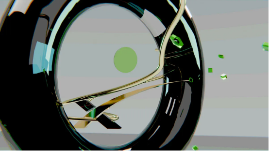
A toroidal inductor features a doughnut-shaped core with wire wound around its circumference. This closed-loop geometry confines magnetic flux within the core material itself. The design naturally suppresses stray magnetic fields, which reduces electromagnetic interference with nearby circuits. Engineers choose this component shape for applications where signal integrity matters, such as audio equipment and data processing systems.
The toroidal structure also delivers a higher inductance-to-volume ratio than traditional cylindrical coils. Designers can achieve substantial inductance values in compact spaces. For example, the ITP Series from ICE Components specifies an inductance range of 10 µH to 1000 µH for high-current toroidal inductors used in power supply filtering.
Common applications include:
· Switch-mode power supplies and DC-DC converters
· Photovoltaic inverters and energy conversion systems
· Motor drives and industrial automation equipment
· EMI filtering and noise suppression circuits
· Lighting control systems and voltage regulation devices
Why Core Material Choice Matters
The core material determines several critical performance metrics. Saturation current represents the maximum operating current an inductor can handle before its core becomes magnetically saturated and inductance sharply decreases. Exceeding this threshold leads to distorted signals, reduced efficiency, or thermal damage. Core losses affect efficiency across the operating frequency range. Inductance stability under DC bias determines whether the component maintains its rated value as current increases.
Different applications prioritize different metrics. A PFC inductor or high-current boost choke demands strong DC bias handling and predictable inductance roll-off. An LLC transformer requires low loss across a frequency range with careful attention to magnetizing current. No single material excels at everything, so engineers must match material properties to application requirements.
Ferrite and iron powder represent the two dominant material families for toroidal cores. Ferrite offers very low losses with high permeability values. Iron powder provides higher saturation flux density and stable inductance under DC bias. The choice between them depends on operating frequency, power level, and which performance metric matters most for the specific design. This Toroidal Inductor Core Material Selection process starts with understanding these fundamental trade-offs.
Ferrite vs. Iron Powder: Key Material Properties
Permeability and Saturation Flux Density
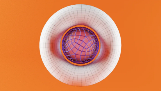
Permeability measures how easily a core material supports magnetic flux. Ferrite materials exhibit high permeability values, typically ranging from 1000 to 15000. This high permeability allows designers to achieve large inductance values with fewer winding turns. Iron powder cores present a different profile, with permeability values typically between 10 and 100. The lower permeability stems from distributed air gaps embedded throughout the material structure.
These air gaps fundamentally change how each material responds to magnetic stress. High-permeability ferrite cores demonstrate sensitivity to flux density variations. When the core approaches saturation, permeability drops dramatically, causing the inductance factor (AL) to decrease sharply. This behavior makes ferrite cores less stable under varying current conditions. Iron powder cores, by contrast, maintain consistent performance because their distributed air gaps lower effective permeability and reduce sensitivity to flux density changes. The AL value remains constant over a wider operating range.
Saturation flux density represents another critical distinction. Ferrite cores saturate at lower magnetic flux densities compared to their iron powder counterparts. This limitation means ferrite inductors reach magnetic saturation at lower currents. Iron powder cores handle substantially higher DC bias before saturation occurs. The following table summarizes these fundamental differences:
Core Type | Permeability vs Saturation Flux Density | Stability |
Ferrite (high μᵣ) | High permeability cores are sensitive to flux density variations; near saturation, permeability drops dramatically, causing AL to decrease. | Less stable, AL varies with current. |
Iron Powder | Distributed air gaps lower effective permeability, making them less sensitive to flux density variations. | More stable, AL remains constant over a wider range. |
Core Loss and Frequency Response
Core loss consists of hysteresis loss and eddy current loss. Hysteresis loss relates to the energy required to magnetize and demagnetize the core material each cycle. Eddy current loss arises from circulating currents induced within the conductive core material. The material's electrical resistivity directly controls eddy current magnitude.
Ferrite materials possess exceptionally high electrical resistivity. This property strongly limits classical eddy-current loss, making ferrite cores highly suitable for high-frequency power conversion. The low electrical conductivity prevents current circulation inside the core, reducing heat generation in high-frequency circuits. Ferrite cores demonstrate exceptional performance across high-frequency ranges with minimal eddy current loss.
Iron powder cores present a different loss profile. A powder core does not automatically qualify as a low-loss solution. Engineers must evaluate its loss density at the actual switching frequency of the application. Iron powder cores exhibit higher core losses at elevated frequencies, particularly above 100 kHz. Their construction suits current handling at low frequencies, typically 50-60 Hz systems, where eddy current losses remain manageable.
· Ferrite Core: Has low electrical conductivity, which prevents the circulation of currents inside the core and reduces core heat in high-frequency circuits. It is noted for exceptional performance in high-frequency ranges with minimal eddy current loss.
· Iron Powder Core: Has higher saturation flux density but is described as suitable for handling currents at low frequencies (50-60 Hz systems), implying higher losses at 100 kHz compared to ferrite.
This frequency-dependent behavior directly influences Toroidal Inductor Core Material Selection. Designers working with switching frequencies above 10 kHz must weigh ferrite's superior loss characteristics against iron powder's saturation advantages. A ferrite core operating at 100 kHz will run cooler and maintain higher efficiency. An iron powder core at the same frequency will generate more heat but can withstand higher DC bias without saturating. The application's priority determines which trade-off proves acceptable.
Performance Comparison for Real-World Applications
High-Frequency Efficiency and Temperature Stability
Ferrite cores demonstrate exceptional efficiency when switching frequencies exceed 10 kHz. Their ultra-low core losses make them the preferred choice for switch-mode power supplies and RF circuits. A ferrite-based inductor operating at 100 kHz maintains high efficiency because eddy current losses remain minimal. This characteristic translates directly into cooler operation and reduced energy waste in compact power converters.
Temperature behavior introduces another critical distinction between the two materials. Ferrite materials possess a Curie temperature limit that varies by specific grade. Beyond this threshold, ferrite loses its magnetic properties entirely. Designers must account for this limitation when operating near high-temperature components or in thermally demanding environments.
Iron powder cores exhibit greater thermal resilience across a wider operating range. Their distributed air gap structure does not suffer from the same temperature-induced permeability collapse. This stability allows iron powder inductors to maintain consistent performance even when ambient temperatures rise substantially. Engineers working in automotive or industrial settings often prefer iron powder for this thermal predictability.
DC Bias Handling and Energy Storage Capability
Iron powder cores excel in applications requiring substantial DC bias handling. Their distributed air gaps prevent early saturation, allowing the inductor to carry higher currents while maintaining stable inductance values. Power factor correction (PFC) inductors and output chokes benefit directly from this behavior. These components must handle significant DC current while preserving their filtering function.
Ferrite cores saturate at considerably lower flux densities. A ferrite inductor subjected to high DC bias experiences a sharp inductance drop once saturation begins. This sudden change disrupts circuit operation and generates excessive heat. Consequently, ferrite suits applications with moderate current levels where high-frequency performance matters more than DC robustness.
Energy storage capability follows the same pattern. Iron powder cores store more energy per unit volume before saturation occurs. Their gradual inductance roll-off provides predictable behavior under varying load conditions. This predictability simplifies circuit design and ensures reliable operation across the full current range. The Toroidal Inductor Core Material Selection process ultimately balances these real-world performance characteristics against application-specific priorities.
A Step-by-Step Guide to Core Material Selection
Decision Process Based on Your Design Requirements
The Toroidal Inductor Core Material Selection process starts with a clear assessment of operating frequency. Ferrite cores suit applications above 100 kHz where their low core losses provide clear efficiency advantages. Iron powder cores perform well in the 1 kHz to 100 kHz range, making them the default choice for many power conversion circuits. Designers working below 1 kHz should consider silicon steel laminations instead.
After establishing the frequency range, engineers assess DC bias current. High DC bias pushes a core toward saturation. Iron powder cores handle this stress much better because their saturation flux density reaches approximately 1.2 T compared to only 0.35 T to 0.45 T for ferrite. A power factor correction inductor carrying 20 A of DC current demands iron powder to maintain stable inductance. A ferrite core would saturate and lose its inductance at a fraction of that current.
The third decision point involves efficiency versus core size. A smaller core reduces physical volume and cost but forces higher flux density, which increases core loss. Engineers use a Pareto front that simultaneously minimizes total power loss and core volume. Iron powder cores allow smaller physical sizes for high-current inductors because their higher saturation flux density lets the designer use fewer turns or a smaller cross-section. Ferrite cores require larger volumes to avoid saturation but run cooler at high frequencies. The following table summarizes the key trade-offs:
Parameter | Ferrite | Iron Powder |
Saturation flux density | 0.35–0.45 T | 1.2 T |
Permeability range | 1,500–3,000 (ungapped) | 10–100 |
Core loss at high frequency | ~40 mW/cm³ | Greater than 1,500 mW/cm³ |
DC bias stability | Poor (gap-dependent) | Fair |
Relative cost | Lowest | Lowest |
Typical application | High-frequency above 200 kHz, low power | Cost-critical, below 50 kHz, non-precision |
Engineers also evaluate permeability consistency across temperature. Ferrite permeability drops sharply above 60 degrees Celsius, which can destabilize inductance in unventilated designs. Iron powder cores maintain more stable permeability across a wider temperature range, making them suitable for thermally demanding environments. Reputable suppliers publish full loss curves measured in watts per kilogram at rated flux density and frequency. Designers should consult these curves to verify that the chosen material meets the thermal budget of the enclosure.
Typical Applications and Industry Examples
High-frequency transformers for switch-mode power supplies use ferrite cores almost exclusively. These designs operate above 100 kHz and require minimal core loss to maintain efficiency. Common-mode chokes also favor ferrite because the high permeability provides strong common-mode rejection with few turns. LLC resonant converters represent another application where ferrite's low loss across a frequency range proves essential.
DC-DC converter output inductors and power factor correction inductors rely on iron powder cores. These components carry substantial DC current and need stable inductance throughout the operating range. The distributed air gap in iron powder provides gradual saturation behavior rather than a sharp collapse. Energy storage applications, such as boost converters in photovoltaic inverters, also benefit from iron powder because the core can store more energy per unit volume before reaching saturation.
Both materials prove viable for toroidal inductors operating above 10 kHz. The 10 kHz boundary serves as a useful starting point, but the final decision depends on the specific combination of current, temperature, and size constraints in the design. A ferrite core at 100 kHz runs cooler but saturates sooner. An iron powder core at the same frequency generates more heat but withstands higher DC bias without failure. This Toroidal Inductor Core Material Selection process requires balancing frequency, current, size, and thermal constraints against one another.
For designs that push the boundaries of either material, designers may consider nanocrystalline or amorphous cores. These alternatives offer higher saturation flux density than ferrite and lower core loss than iron powder, but they come with higher cost and limited availability. The ferrite versus iron powder decision remains the most practical starting point for the majority of power electronics applications.
Designers choose ferrite for high-frequency, low-loss applications with moderate power. They select iron powder for high-power, high-DC-bias designs requiring stable inductance and strong saturation. No single core material works best for every design. The optimal choice depends on operating frequency, power level, and performance priorities. Engineers should use the Toroidal Inductor Core Material Selection guide as a checklist for their next project. Both materials remain viable above 10 kHz, depending on the application.
FAQ
What happens when a ferrite core saturates?
Saturation causes inductance to drop sharply. The core loses its magnetic properties temporarily. Current rises rapidly through the winding. Circuit performance degrades. Excessive heat may develop. Designers must account for this behavior when setting maximum current limits. Ferrite cores saturate around 0.35 to 0.45 Tesla.
Can iron powder cores operate at high frequencies?
Iron powder cores work above 10 kHz, but core losses increase significantly. Above 100 kHz, losses become substantial. Ferrite cores offer lower losses at these frequencies. Engineers should examine loss density curves from manufacturers. These curves show watts per kilogram at specific frequencies and flux densities. The application determines acceptable loss levels.
How does operating temperature affect core material choice?
Ferrite permeability drops sharply above 60 degrees Celsius. This change destabilizes inductance values. Iron powder maintains stable permeability across wider temperature ranges. Ferrite also has a Curie temperature limit. Beyond this point, magnetic properties disappear entirely. Thermal environments influence the final Toroidal Inductor Core Material Selection decision.
Which material offers better cost efficiency?
Both materials rank among the lowest-cost core options. Ferrite cores cost slightly less per unit volume. Iron powder cores may allow smaller physical sizes for high-current designs. Smaller cores reduce overall component cost. The total cost depends on required inductance, current handling, and operating frequency. Designers should compare complete solutions, not just material prices.