English
 Vietnamese
 Italian
 Spanish
 Thai
 Japanese
 Portuguese
 Korean
 Russian
 French
 German
 Polish
 Indonesian
Gujing Supports Automotive Inductor Testing
Gujing Supports Automotive Inductor Testing
An automotive customer approached Gujing after encountering current-related performance issues with an inductor supplied by another manufacturer. With the original supplier unable to provide the technical analysis and testing support needed for the investigation, the customer turned to Gujing for further evaluation.
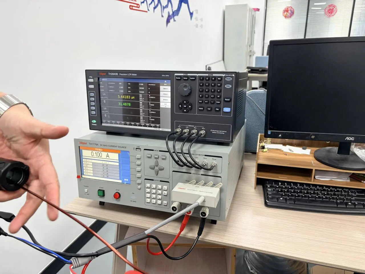
The investigation focused on measuring inductance across a range of DC bias currents and comparing the results after changing the winding configuration.
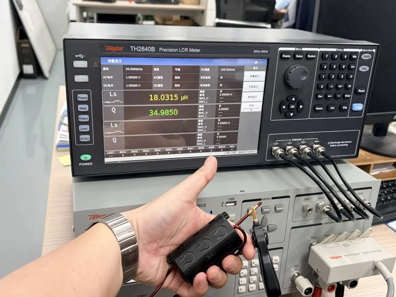
Evaluating Inductance Under DC Bias
A no-load inductance measurement alone does not show how an inductor behaves as operating current increases. For this project, the test procedure was designed to record inductance at successive current levels, providing a clearer picture of the component’s DC bias characteristics.
The evaluation used the following test conditions:
- Conductor arrangement: A conductor passed through the magnetic core, with a recommended cross-sectional area of 4 mm².
- Test frequency: 20 kHz.
- Measurement mode: Series inductance, or Ls.
- Starting DC bias current: 0 A.
- Current increment: 0.5 A.
- Maximum DC bias current: 20 A.
- Data recording: Inductance recorded at each current step.
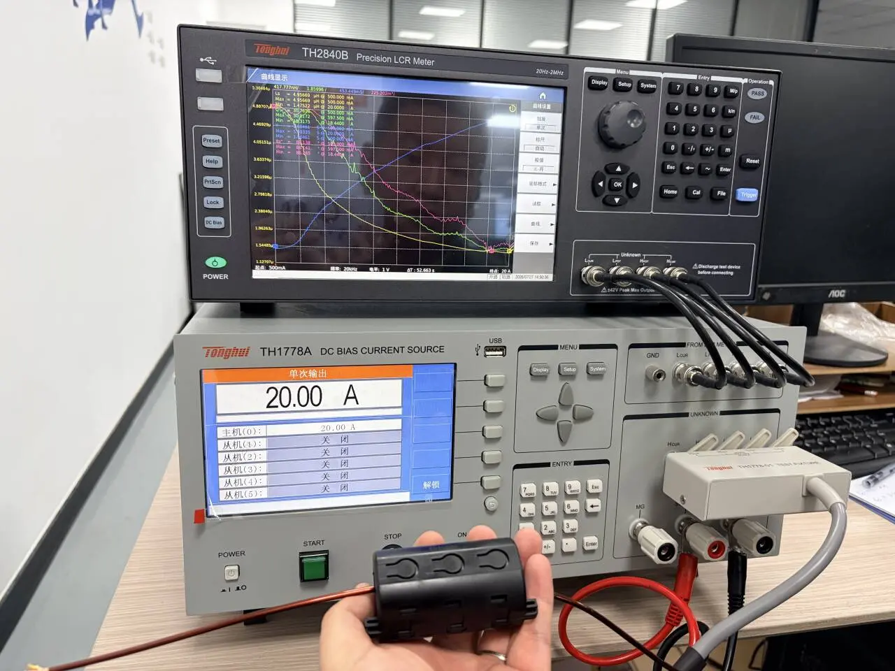
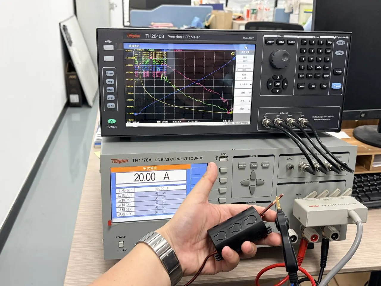
This procedure produces an inductance-versus-current profile, allowing the technical team to examine how inductance changes as DC bias increases.
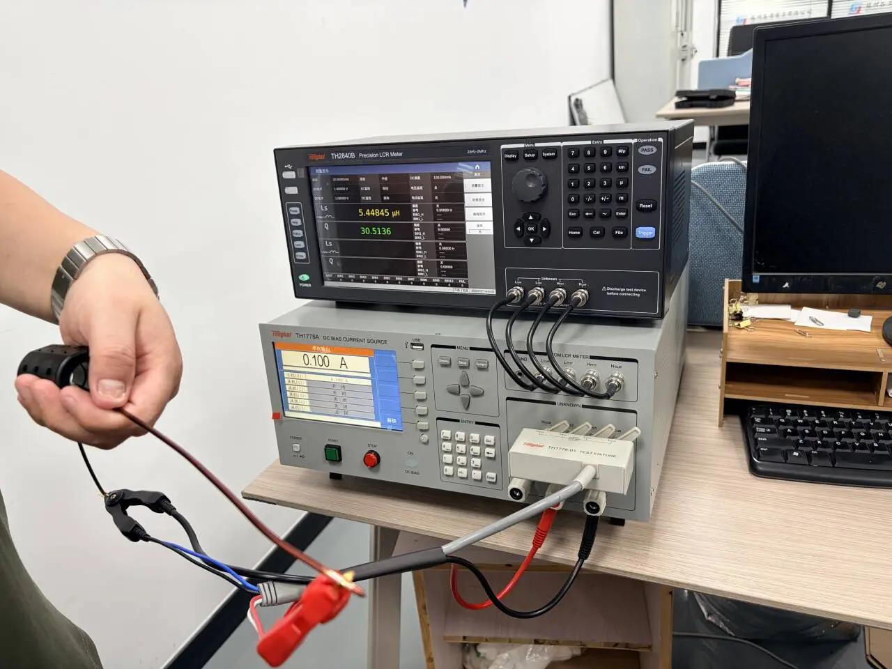
Comparing Different Winding Configurations
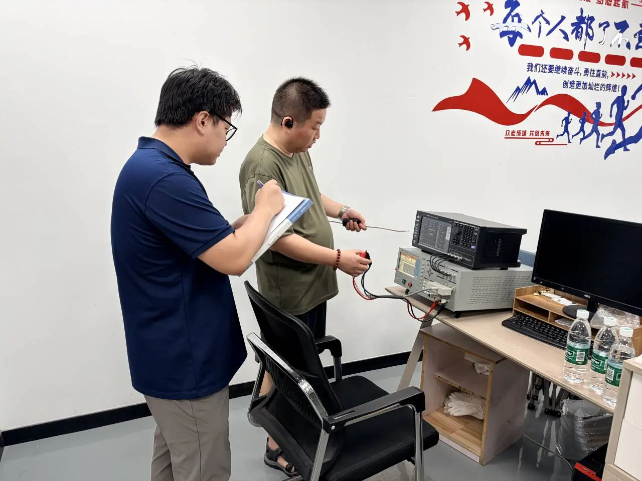
The next step was to change the winding configuration and repeat the same current sweep.
Keeping the test frequency, measurement mode and current increments consistent provides a basis for comparing the winding configurations. Rather than relying on a single measurement, the analysis considers the inductance response across the full tested current range.
The comparison can help identify how winding changes affect DC bias performance and guide further evaluation of the magnetic core and winding design.
Turning Measurements into Engineering Decisions
For a current-related inductor issue, useful technical support requires both measurement capability and a structured method of interpreting the results.
In this project, the combination of stepped DC bias testing and repeated winding comparisons provided a practical framework for investigating the customer’s concern. Final design decisions depend on the measured data and the application’s required operating conditions.
Discuss Your Inductor Testing Requirements
If your inductor shows unexpected behavior under load, share its operating current, test frequency, inductance requirements and winding details with Gujing.
Gujing can help evaluate the component’s DC bias characteristics and investigate potential adjustments to the core and winding configuration.