English
 Vietnamese
 Italian
 Spanish
 Thai
 Japanese
 Portuguese
 Korean
 Russian
 French
 German
 Polish
 Indonesian
Custom Toroidal Inductor Winding Tips for Clean Switching
Clean switching in high-power circuits depends on winding geometry that controls parasitic capacitance and leakage inductance. Downstream filtering cannot repair a poor toroid build.
The winding method is the strongest design lever an engineer controls. Layer count, turn spacing, and return-path routing decide how toroidal inductors behave. Ringing, overshoot, and EMI trace back to how someone wound the core.
Poor windings raise leakage inductance. That leakage drives voltage spikes across the switch. Those spikes stress components and radiate noise.
Engineers build custom toroidal inductor designs in sequence. Core selection comes first. Winding style follows. Wire choice, parasitic control, and bench validation complete the process. Each step shapes the next.
Core Choice for Custom Toroidal Inductor Builds
Material and Frequency Match
The core material sets the loss and frequency ceiling for every toroidal inductor. Ferrite offers high permeability and high resistivity. It suits high-frequency switching above 200 kHz because core losses stay near 40 mW/cm³. Ferrite saturates at 0.35–0.45 T, so designers must watch magnetic saturation in high-power circuits.
Iron powder cores hold inductance steady under DC bias. Each particle carries insulation, which creates a distributed air gap. These cores reach 1.2 T saturation flux density. However, core losses exceed 1,500 mW/cm³ above 100 kHz, so they fit lower-frequency, bias-heavy designs.
Amorphous metal cores reach 1.4–1.56 T saturation flux density with low loss. They serve fast switching and high-frequency needs. Nanocrystalline variants handle low-frequency, high-field work without saturating.
Core Material | Saturation Flux Density | High-Frequency Core Loss |
Ferrite | 0.35–0.45 T | ~40 mW/cm³ |
Iron powder | 1.2 T | >1,500 mW/cm³ |
Amorphous metal | 1.4–1.56 T | Low (value not specified) |
Gujing leverages more than 20,000 magnetic core material formulations. The company builds a custom toroidal inductor to user-specified inductance values, dimensions, and materials.
Size and Saturation Headroom
Core size must leave saturation headroom for peak switching current. A core that runs close to its saturation current clips inductance during load steps. That clipping produces ringing and overshoot. High-power designs need generous margin between operating current and the saturation current limit.
Larger toroidal core sizes raise the saturation current threshold. They also spread heat across more surface area. Engineers should compare peak current against the saturation current rating at the worst-case temperature. This step protects the windings and keeps waveforms clean.
Gujing's engineering team supports material selection and structural optimization from prototype through mass production.
Toroidal Inductor Wire Windings That Stay Clean
Single-Layer Windings for Low Capacitance
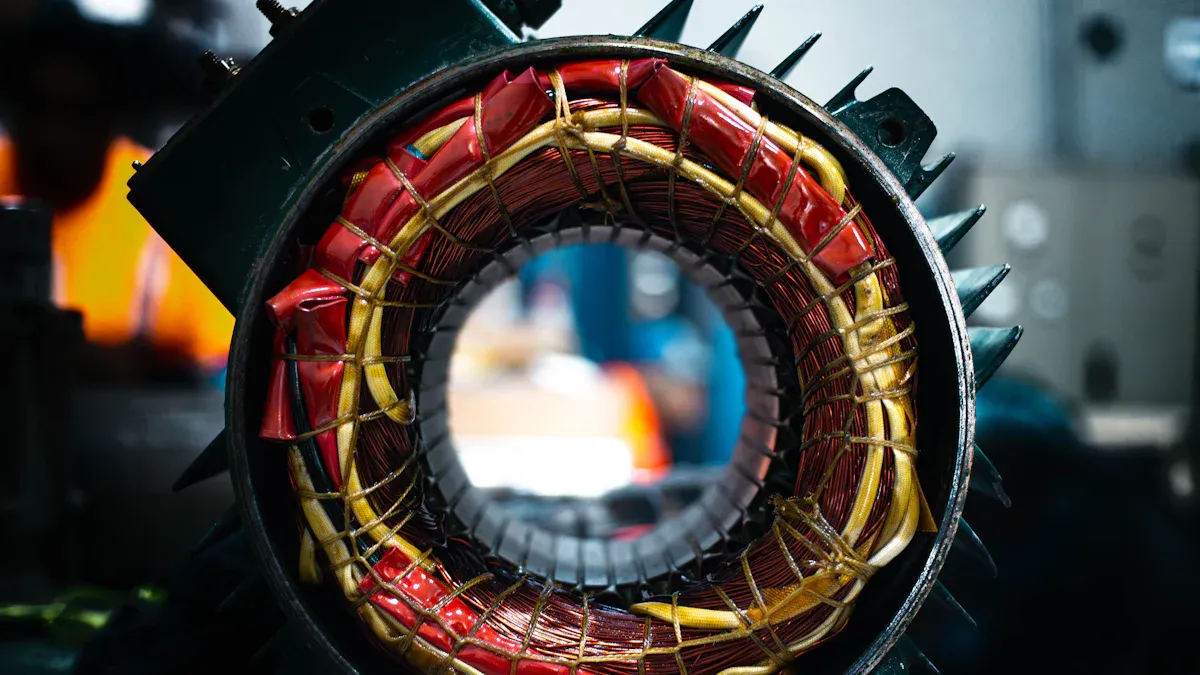
A single-layer winding places every turn side by side around the core in one pass. This layout keeps inter-winding capacitance low because adjacent turns sit at similar voltages. The end-to-end capacitive bridge stays weak, so the self-resonant frequency remains moderate, typically 5–15 MHz. A high self-resonant frequency lets the inductor hold its inductance well into the switching band.
Single-layer windings suit most offline converters, DC-DC stages, and EMI filters. They work best when the required inductance fits in one pass of wire around the core. Full coverage winding wraps the conductor around the entire core. This approach minimizes leakage inductance and confines flux within the core, which reduces stray fields and radiated EMI.
Engineers choose single-layer construction when clean switching matters more than raw inductance. The winding process stays simple, and the toroidal inductor coil behaves predictably across the current range.
Multi-Layer and Interleaved Windings for Higher Inductance
Higher inductance demands more turns, and more turns demand more layers. A multi-layer winding stacks wire over previous passes. This raises inductance, but inter-layer capacitance climbs from high to very high. The self-resonant frequency drops to roughly 1–5 MHz, often 5 to 10 times lower than a single-layer equivalent. That shift signals a substantial rise in parasitic capacitance.
Interleaving changes the magnetic coupling and leakage distribution. This technique reduces parasitic capacitance and helps limit high-frequency EMI. Designers balance the trade-off by limiting layer count, spacing layers apart, and interleaving where the circuit allows.
Winding Parameter | Influence on Leakage Inductance | Influence on EMI |
Full coverage winding | Minimizes leakage by wrapping the conductor around the entire core | Confines flux, reducing radiated EMI |
Sector winding | Intentionally increases leakage by leaving part of the core unwound | Higher leakage can couple to nearby circuits |
Single vs multi-layer | Affects arrangement and parasitic capacitance | Extra layers alter high-frequency EMI behavior |
Interleaving | Changes magnetic coupling and leakage distribution | Reduces parasitic capacitance, limiting high-frequency EMI |
Mechanical tension and insulation quality keep the conductor geometry stable. Stable, tight windings reduce vibration-induced field variation and related EMI.
Fine-Tuning Inductance After Winding
Inductance rarely lands exactly on target after the first pass. Engineers fine-tune it by slightly stretching or compressing turns along the core. Spreading turns apart lowers inductance; pressing them together raises it. Moving a tap to a different turn also shifts the effective number of turns.
These adjustments change the winding turns without rewinding the part. A small shift in turn spacing alters inductance enough to meet tolerance. The same adjustment affects parasitic capacitance, so engineers check both values after each change.
Gujing builds a custom toroidal inductor to user-specified inductance values, dimensions, and materials. The company's automated lines and full batch traceability support consistent, repeatable builds. Each toroidal core receives the same winding treatment, so inductance stays stable from unit to unit.
For any toroidal inductor, the wire windings decide how cleanly the circuit switches. Single-layer designs favor low capacitance. Multi-layer and interleaved designs trade capacitance for inductance. Careful tuning brings the part back to target.
Wire Selection for High Current Toroidal Inductors
Stranded vs. Solid Wire Trade-Offs
Stranded wire bundles many thin strands into one conductor. Each strand carries a fraction of the total current, so skin-effect loss drops at high frequencies. The bundle also raises inter-strand capacitance, which can lower the self-resonant frequency of the toroidal inductors. Engineers accept this trade-off when switching losses dominate.
Solid wire offers a simpler build. It holds its shape around the core and resists vibration. A solid conductor suits low-frequency, high-current inductors where skin depth exceeds the wire radius. The table below compares both options.
Wire Type | Skin-Effect Loss | Capacitance | Mechanical Stiffness |
Stranded | Lower | Higher | Flexible |
Solid | Higher | Lower | Stiff |
Flat copper wire windings serve EV chargers, renewable energy inverters, and industrial switching power supplies. The rectangular cross-section fills more of the core window, which raises current-carrying capacity and lowers DCR. Flat wire also improves high power handling in compact footprints.
Turn Spacing and Insulation
Consistent turn spacing controls leakage inductance. Even spacing spreads the magnetic field and reduces localized flux concentration. Uneven turns create gaps that allow flux to escape the core, which raises leakage and EMI. A steady hand or an automated winding line keeps spacing uniform.
Insulation thickness sets the breakdown margin between adjacent turns. Thicker insulation raises the voltage rating but consumes window area. That reduction forces a larger core or a smaller wire gauge. Engineers balance insulation against the number of turns and the saturation current target.
Wire gauge selection follows the current requirement. A larger gauge lowers resistance and heat, but it stiffens the wire and limits how tightly it bends around the core. Low DCR toroidal inductors often use the largest gauge that fits the window without stressing the insulation.
Gujing's automated winding lines and full batch traceability support consistent, repeatable custom builds. Each toroidal inductor and coil receives uniform turn spacing and insulation treatment.
Cutting Parasitics in Toroidal Inductors
Geometry That Lowers Inter-Winding Capacitance
Inter-winding capacitance creates a high-frequency bypass path around the core. Reducing this capacitance keeps the self-resonant frequency high and preserves clean switching. The geometry of toroidal inductors determines how much capacitance appears between adjacent turns. Engineers who design toroidal inductors must prioritize even spacing around the toroidal core. When turns sit close together, the electric field between them grows stronger and raises capacitance. Even spacing distributes that field across a larger distance and lowers the stored charge. Full coverage winding wraps every turn around the entire core. This arrangement keeps the winding tight against the magnetic path and minimizes stray fields. Toroidal inductors benefit from this consistent turn layout because it preserves the target inductance value.
Bobbin-assisted layering alters parasitic capacitance by controlling turn position. Interleaving primary and secondary windings improves magnetic coupling but adds a small capacitance increase. Shielded layers between the windings reduce common-mode noise and EMI. Mechanical clamps or potting compounds hold the winding geometry fixed. Stress from vibration or thermal cycling shifts turns and changes capacitance. A stable winding maintains consistent parasitic values across temperature changes. Avoiding unintended air gaps through tight process control prevents capacitance drift. A continuous, seamless winding around the core keeps the electric field uniform. The toroidal core benefits greatly from this approach.
Geometry / Design Change | Effect on Inter-Winding Capacitance | Effect on EMI / Noise |
Bobbin-assisted layering and turn insulation | Alters parasitic capacitance; interleaving increases capacitance slightly | Shielded layers help reduce common-mode noise and EMI |
Careful interleaving of windings | Small increase in capacitance | Improves coupling and lowers leakage; may reduce EMI via tighter coupling |
Toroidal closed magnetic path (no air gaps) | Not directly addressed, but minimizes leakage inductance | Minimizes fringing fields and stray fields, suppressing EMI |
Mechanical clamps or potting to maintain shape | Prevents winding stress that could alter capacitance | Suppresses noise and prevents core deformation |
Avoiding air gaps (tight process control) | Prevents unintended capacitance changes from stress | Maintains low leakage inductance and stable flux distribution |
Return-Path Routing for Low Leakage
Leakage inductance arises when flux escapes the core and couples to nearby circuits. A short return lead placed close to the toroidal core reduces that leakage. The return path carries current back from the load. If that path runs far from the core, the loop area grows and flux radiates outward. Keeping the lead tight against the core confines the magnetic field. This attention to detail improves inductance stability and reduces noise coupled into adjacent traces. Toroidal inductors require this careful routing for clean operation across the full current range.
The toroidal core uses a continuous, doughnut-shaped closed-loop structure that eliminates air gaps. This closed-loop design reduces magnetic leakage by up to 80% compared to open-core structures. The reduction minimizes electromagnetic interference and energy losses. Engineers who route the return wire along the core surface reinforce this advantage. The number of turns around the core interacts with the return path to determine overall leakage behavior.
The closed-loop design offers several benefits for toroidal inductors:
1. Cores are designed as closed magnetic loops, allowing flux to circulate continuously.
2. This structure minimizes gaps that would otherwise increase reluctance.
3. It reduces magnetizing current requirements.
4. A well-designed core minimizes leakage flux, improving voltage regulation and enhancing efficiency.
5. Core geometry and winding placement work together to control flux paths.
Core type influences leakage behavior. A comparison shows the toroid's advantage.
Core type | Salient features | Typical inductor use |
Toroid | Closed magnetic path, low leakage flux, good magnetic efficiency | Power inductors, EMI chokes, current transformers |
Pot core | Stronger shielding because it encloses much of the winding | Not specified |
Toroidal common mode inductors feature a closed-loop design with low magnetic leakage and superior noise suppression performance.
Gujing's closed-loop magnetic core design suppresses flux leakage and supports EMC compliance. The toroidal inductors and coils from Gujing leverage this closed-loop architecture to minimize parasitic effects. Each custom toroidal inductor receives winding placement that controls flux paths. The result is stable inductance, low core losses, and clean switching across the operating current range. Toroidal inductors from Gujing deliver consistent performance for demanding power applications.
Validating Custom Toroidal Inductor Windings
Bench Measurements That Reveal Ringing
Engineers should measure three parameters before installing any custom toroidal inductor: inductance, leakage inductance, and self-resonant frequency. An LCR meter at the intended switching frequency confirms the inductance value. A shorted-secondary test reveals leakage inductance, which drives voltage spikes across the switch. A sweep of self-resonant frequency shows where the core stops behaving like an inductor.
These measurements expose problems that a datasheet cannot. A part with low inductance and high leakage will ring hard on the switching node. A part with a low self-resonant frequency will lose its inductive character inside the operating band. The table below summarizes what each measurement reveals.
Measurement | What It Reveals | Warning Sign |
Inductance | Energy storage at operating frequency | Value drifts from target |
Leakage inductance | Spike energy coupled to the switch | High value raises overshoot |
Self-resonant frequency | Upper limit of inductive behavior | Low value sits inside switching band |
Iterating Until Waveforms Are Clean
A scope probe on the switching node shows the real behavior of the toroidal inductors and coils under load. Ringing appears as damped oscillation after each edge. Engineers correlate that ringing with winding changes. Spreading turns apart lowers capacitance and pushes the ring frequency higher. Adding a layer raises capacitance and pulls it lower.
Each iteration should change one variable. Rewind the core with different turn spacing, then re-measure. Adjust the wire gauge, then re-measure. This disciplined winding process isolates the cause of each waveform change. The current through the inductor and the voltage across it tell the full story.
Gujing's automated winding lines and full batch traceability support consistent, repeatable custom builds. Every toroidal inductor and coil leaves the line with uniform windings, so measurements from one unit predict the next. Engineers can trust that a validated design will repeat in production for switching power supplies and other demanding applications.
Clean switching comes from deliberate choices made before the inductor reaches the board. Engineers select the core first, then the winding style, then the wire, then parasitic control, then validation. Each step shapes how toroidal inductors handle current.
Readers should treat the first winding as a prototype. They measure inductance, leakage, and ringing, then adjust turn spacing or wire gauge. Toroidal inductors and coils improve through iteration, not assumption.
Disciplined practice pays off. Toroidal inductors run cooler, radiate less EMI, and switch predictably. The core, the winding, and the wire all carry current with stability. Toroidal inductors built this way reward the engineer at every load step.
FAQ
How does an engineer choose the right core material for a toroidal inductor?
The switching frequency and loss target drive the choice. Ferrite suits high-frequency designs above 200 kHz. Iron powder handles DC bias at lower frequencies. Amorphous metal serves fast switching with high saturation flux density. Gujing offers more than 20,000 magnetic core material formulations for custom builds.
When should a designer pick a single-layer winding over a multi-layer one?
A single-layer winding keeps inter-winding capacitance low and holds a higher self-resonant frequency. It works when the target inductance fits in one pass around the core. Multi-layer windings raise inductance but add capacitance. Engineers choose layers only when the circuit needs more turns.
What wire type works best for high current toroidal inductors?
Stranded wire lowers skin-effect loss at high frequencies but raises capacitance. Solid wire stays simple and stiff for low-frequency designs. Flat copper wire fills the core window and improves high power handling. The switching frequency and current requirement decide the best fit.
How does turn spacing affect parasitic capacitance and leakage?
Even turn spacing spreads the electric field and lowers inter-winding capacitance. Uneven turns create gaps that let flux escape the core, which raises leakage. Consistent spacing keeps the self-resonant frequency high. Automated winding lines hold spacing uniform from unit to unit.
What measurements confirm a clean toroidal inductor winding?
Engineers measure inductance, leakage inductance, and self-resonant frequency before installation. A scope probe on the switching node reveals ringing after each edge. Each iteration changes one variable, such as turn spacing or wire gauge. Gujing's batch traceability supports repeatable custom builds.